I have two fundamental “rants” about flight simulator scenery, and the way people discuss it, market it, compare it, and evaluate it. The rants basically go like this:
- Mesh resolution (that is, the spacing between elevation points in a mesh) is a crude way to measure the quality of a mesh. It is horribly inefficient to use 5m triangles to cover a flat plateau just because you need them for some cliffs.
- At some point, the data in a very high mesh becomes misleading. You have a 5m mesh. Great! Are you measuring a 5m change in elevation, or is that a parked car that has been included in the surface?
X-Plane uses an irregular mesh to efficiently use small triangles only where they are needed. I have some pictures on this here.
But it brings up the question: how good is a mesh? If you make a base mesh with MeshTool using a 10m input DEM (the largest DEM you can use right now), the smallest triangles might be 10m. But the quality of the mesh is really determined by the mesh’s “point budget” – that is, the number of points MeshTool was allowed to add to minimize error.
MeshTool beta 4 will finally provide authors with some tools to understand this: it will print out the “mesh statistics” – that is, a measure of the error between the original input DEM and the triangulation. Often the error* from using only 1/6th of the triangles from the original DEM might be as little as 1 meter.
I spent yesterday looking at the error metrics of the meshes MeshTool creates. I figured if I’m going to show everyone how much error their mesh has with a stats printout, I’d better make sure the stats aren’t terrible! After some debugging, I found a few things:
-
Vector features induce a lot of “error” from a metrics standpoint. Basically when you induce vector features, you limit MeshTool’s ability to put vertices where the need to be to reduce meshing error. The mesh is still quite good even with vectors, but if you could see where the error is coming from, the vast majority will be at vector edges.
For example, in San Diego the vector water is sometimes not quite in the flat part of the DEM, and the result is an artificial flattening of a water triangle that overlaps a few posts of land. If that land is fairly steep (e.g. it gains 10+ meters of elevation right off the coast) we’ll pick up a case where our “worst” mesh error is 10+ meters. The standard deviation will be
-
The whole question of how we measure error must be examined. My normal metric is “vertical” error – for a given point, how much is the elevation different. But we can also look at “distance” error: for a given point, how close is the nearest mesh point from the ideal DEM?
“Distance” mesh point gives us lower error statistics. The reason is because when we have a steep cliff, a very slight lateral offset of a triangle results in a huge vertical error, since moving 1m to the right might drop us 20 meters down. But…do we care about this error? If the effective result is the same cliff, offset laterally by 1m, it’s probably more reasonable to say we have “1m lateral error” than to say we have “20m vertical error”. In other words, small lateral errors become huge vertical errors around cliffs.
Absolute distance metrics take care of that by simply measuring the two cliff surfaces against each other at the actual orientation of the cliff. That is, cliff walls are measured laterally and the cliff floor is measured vertically. I think it’s a more reasonable way to measure error. One possible exception: for a landing area, we really want to know the vertical error, because we want the plane to touch pavement at just the right time. But since airplane landing areas tend to be flat, distance measurement becomes a vertical measurement anyway.
Unnatural Terrain
So there I am working with a void-filled SRTM DEM for KSBD. I have cranked the mesh to 500,000 points to measure the error (which is very low, btw…worst error 3m and standard deviation less than 15 cm.
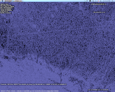
But what are those horziontal lines of high density mesh?
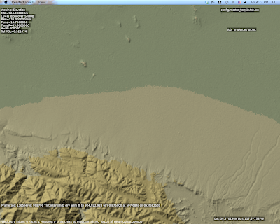
I wasn’t sure what those were, but they looked way too flat and regular. So I look at the original DEM and I saw this:
Ah – there are ridges in the actual DEM. Well that’s weird. What the heck could that be?
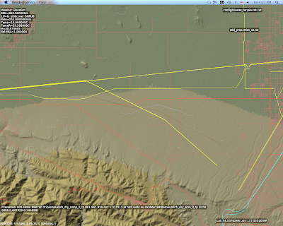
This is a view with vector data – and there you go. Those are power lines.
The problem in particular is that SRTM data is “first return” – that is, it is a measurement of the first thing the radar bounces off of from space. Thus SRTM includes trees, some large buildings, sky scrapers, and all sorts of other gunk we might not want. A mesh in a flight simulator usually represents “the ground”, but using first return data means that our ground is going to have a bump any time there is something fairly large on that ground. The higher the mesh res, and the lower the mesh error, the more of this real world 3-d coverage gets burned into the mesh.
So Do We Really Care About 5m DEMs?
The answer is actually yes, yes we do, but maybe not for the most obvious reasons.
The problem with raster DEMs (that is, an elevation as a 2-d grid of heights) is that it doesn’t handle cliffs very well. A raster DEM cannot, by its very format, handle a truly vertical cliff. In fact, the maximum slope it can create is based on
arctan(cliff height / DEM spacing)
Which is math to say: the tighter your DEM spacing, the higher the maximum slope we can represent for a given cliff at a certain height. Note that the total cliff height matters too, so even a crude 90m DEM like SRTM can represent a canyon if it’s really huge**, but we need a very high res DEM to get shorter vertical surfaces.
So the moderated version of my rant goes something like this:
- High res DEMs input DEMs are necessary to represent small terrain features that are steep if we are using raster DEMs.
- High res meshes are not necessary – we only need res for part of the mesh where it counts.
- Let’s not use mesh res to represent 3-d on the ground, only the ground itself.
There is another way to deal with elevation besides DEMs, and in fact it is used for LIDAR data (where the resolution is so high that a raster DEM would be unusable): you can represent a as a series of vector contour lines in 3-d. The beauty of contour lines is that they represent cliffs no matter how steep (up to vertical), and you don’t need a lot of storage if the ground is not very intricate.
The meshing data format inside MeshTool could probably be made t
o work with contours, but I haven’t seen anyone with high quality contour data yet. We’ll probably support such a feature some day.
* Really this should be “the additional error”, because when you get a DEM, it already has error – that is, the technique for creating the DEM will have some error vs. the real world. For example, if I remember right (and I probably do not) 90% of SRTM data points fall within 8m vertically of the real world values. So add MeshTool and you might be increasing the error from 8m to 9-10m, that is, a 12-25% increase in error.
** For the SRTM this might be a moot point – the SRTM has a maximum cliff slope in certain directions defined by the relationship between the shuttle’s orbit and the latitude of the area being scanned. The maximum cliff at any point in the SRTM is 70 degrees, which can be represented by a 247 m cliff using a pair of 90m posts.
"but using first return data means that our ground is going to have a bump any time there is something fairly large on that ground"
This is already a problem in flat areas (eg. Saskatchewan). The flat terrain has numerous 'building bumps'. When I place an object, such as a grain elevator, it is often perched on a bump.
The tools currently available to correct this are neither GUI nor particularly easy to use.