WED 1.6 in combination with X-Plane 11.10 or newer now includes an integrated ‘Terminal Kit’, comprising facades and supporting objects that are dedicated to the creation of modern airport terminals. This can be found in the WED library hierarchy at “ lib/airport/Modern_Airports/Terminal_kit “. The Terminal Kit is entirely modular, with all parts designed to work together.
The basic concept is for the artist to utilize specific facades for corresponding parts of the building. For example, the kit features one facade for ground floor structures, and another for floors above. This approach asks a little more of the artist, because the facade footprint may need to be replicated multiple times, for each individual floor. However, this method offers far greater possibilities for the design of the structure. Windows, doors or gates may be placed exactly where the artist chooses, without this being restricted by the nature of the adjacent structure.
Key components of the Terminal Kit are prefixed with “ term_ ” so these can be easily filtered in the WED library hierarchy. These are further divided into three logical groups:
The first group ( term_building_.. ) is dedicated to the construction of the main building.
The second group ( term_bridge_.. ) is dedicated to the construction of connecting bridges.
The third group ( term_roof_.. ) is dedicated to the construction of the various roofing options.
Diagram illustrating basic Terminal Kit facade usage:
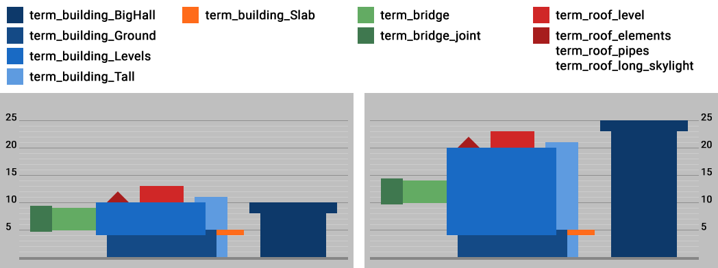
Most facades will comprise several floors, and as you can see, each floor must have an absolute height in units of 5 – namely 5, 10, 15, 20, or 25 meters (one exception is described later).
Diagram illustrating height and elevation options for Terminal Kit facade modules:

Note that roof elements are compatible with height levels (5, 10, 15, 20 and 25 meters). Artists may place them on” _Ground “, “ _Levels “, “ _Slab ” and “ _BigHall ” modules. However, roof components may not be placed on “ _Tall ” modules.
Terminal Kit Components
term_building_…
term_building_Ground_XX.fac
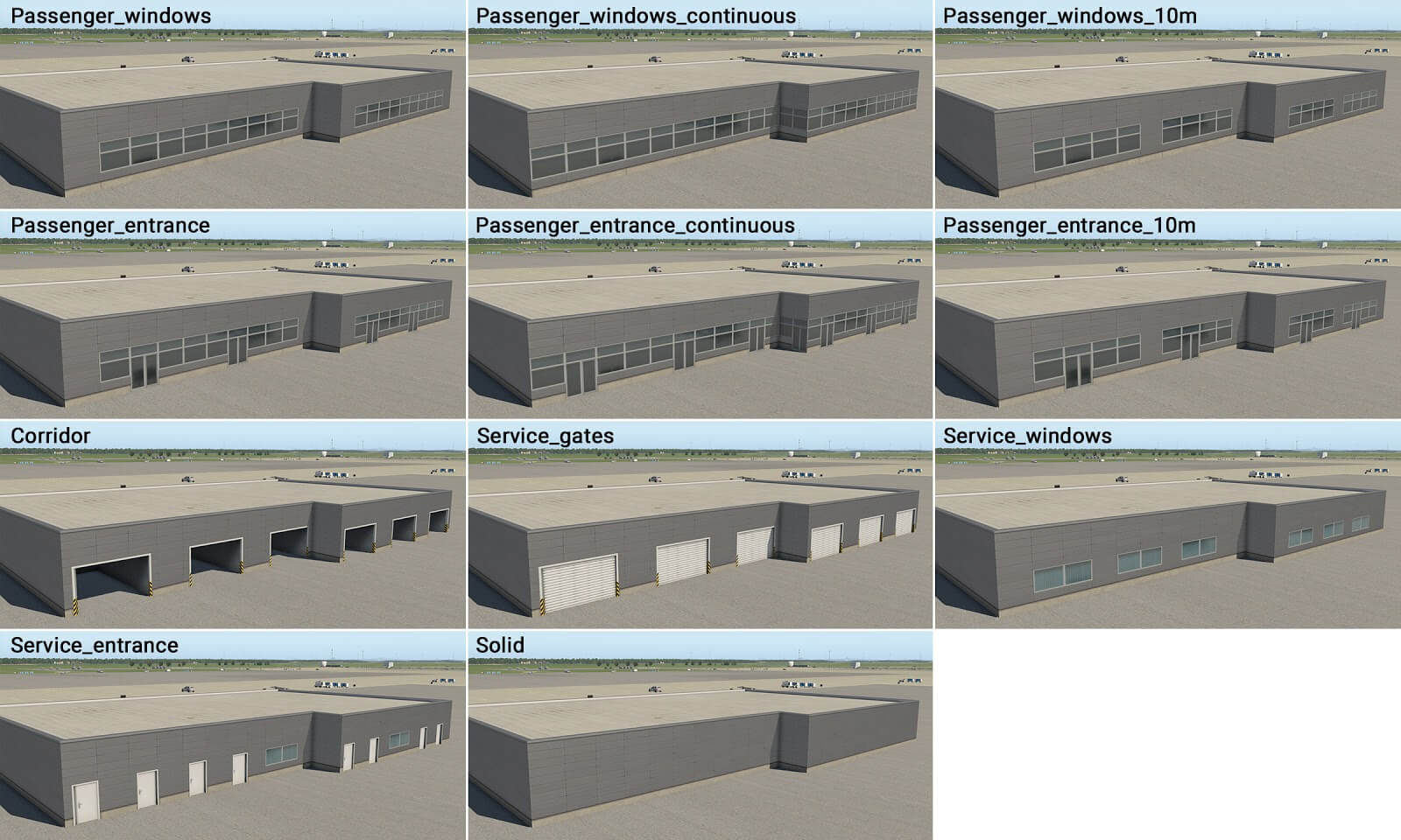
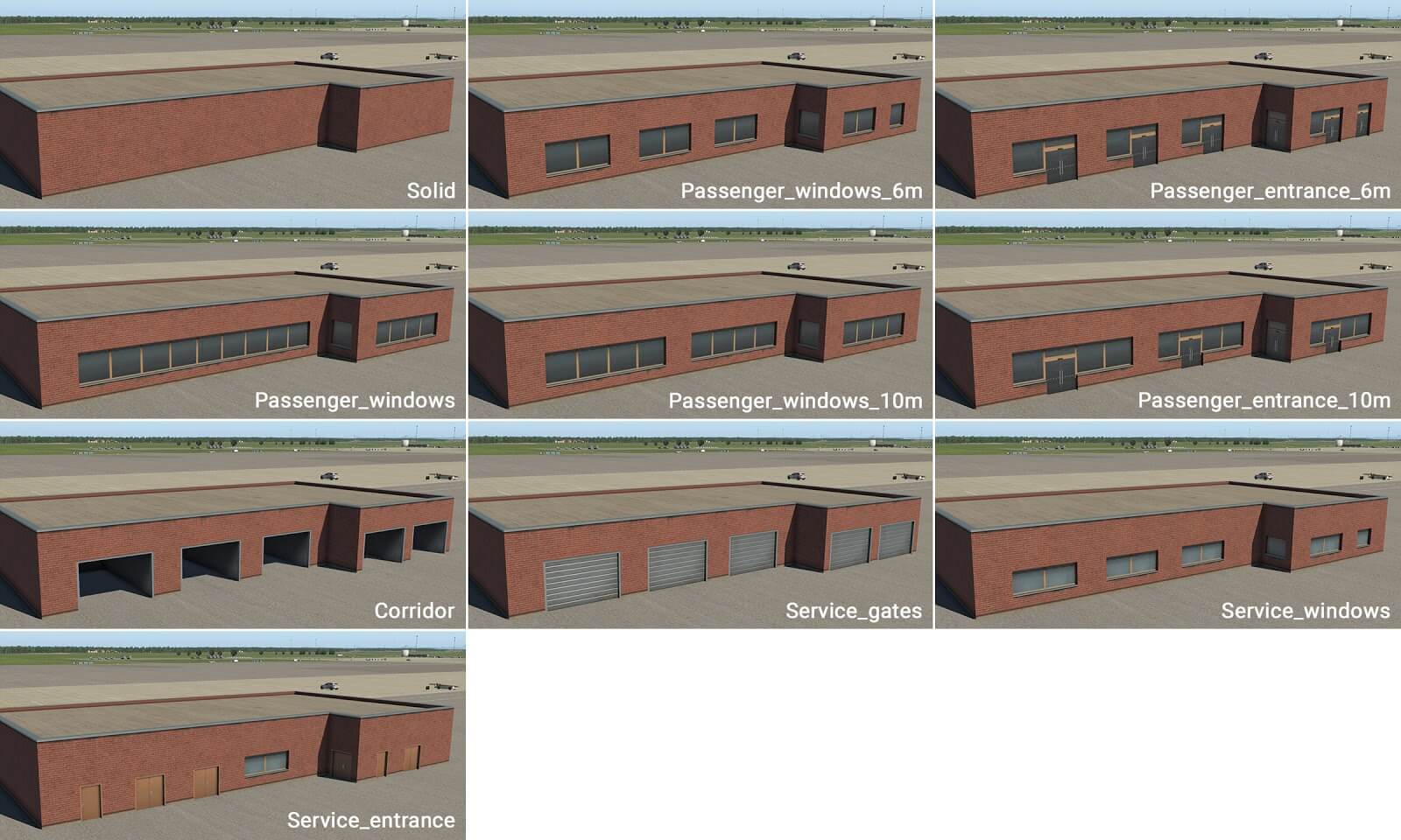
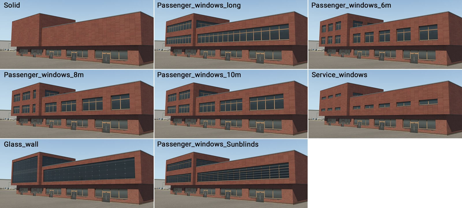
This is the first key component of a building. It has just one ground floor, and its purpose is to replicate the street level of a modern airport terminal. However it can also be used to create any single-floor building, and the artist may use it accordingly. This module has several wall-types–passenger windows, doors, service entrances and gates.
Sometimes three variants of passenger windows and entrances exist. This is a general principle which you will also find in other modules. The first variant ( _windows ) is designed for whole walls, meaning the facade comprises solid segments at both ends. However, sometimes the artist may require contiguous windows spanning the corners, and this is supported with the “ _windows_continuous ” variant. A third variant ( _windows_XXm ) is for long whole walls constructed in units of “XX” meters, with solid segments at either end. Any combination of these variants may be used together, to replicate the desired structure.
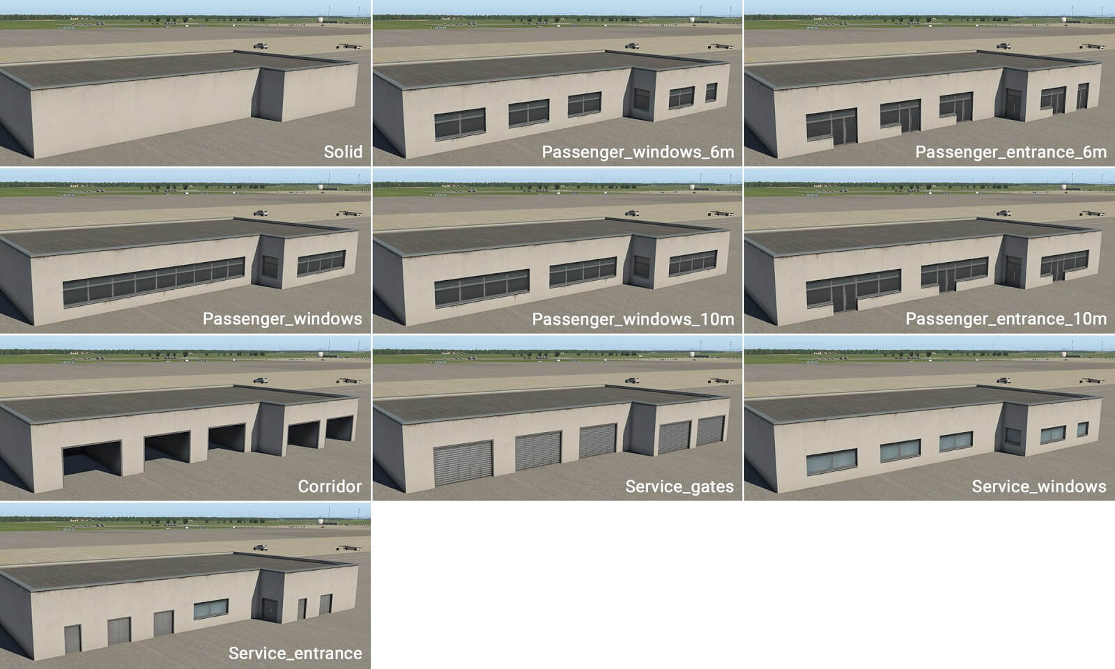
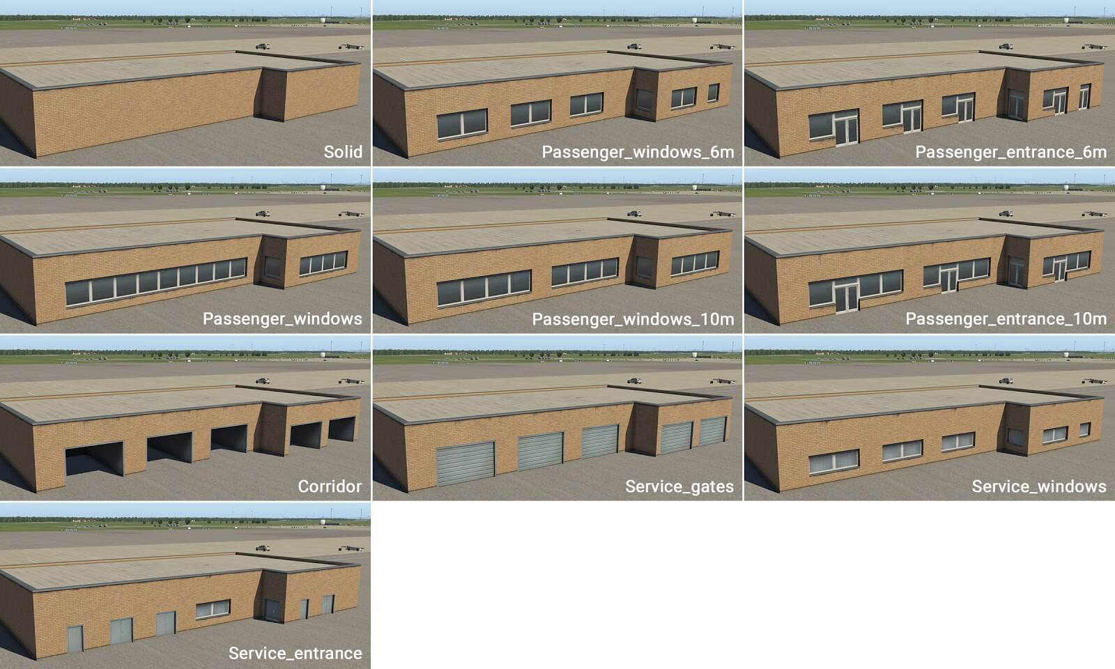
There are four stylistic variants in X-Plane 11.20 and newer:
term_building_Ground_01.fac
term_building_Ground_02.fac
term_building_Ground_03.fac
term_building_Ground_04.fac
term_building_Levels_XX.fac
This is the second key component of a building. It is designed for (up to) three levels above ground. This module forms the “main” body of the terminal, and also has several types of walls (most of which have windows).
term_building_Levels_01.fac
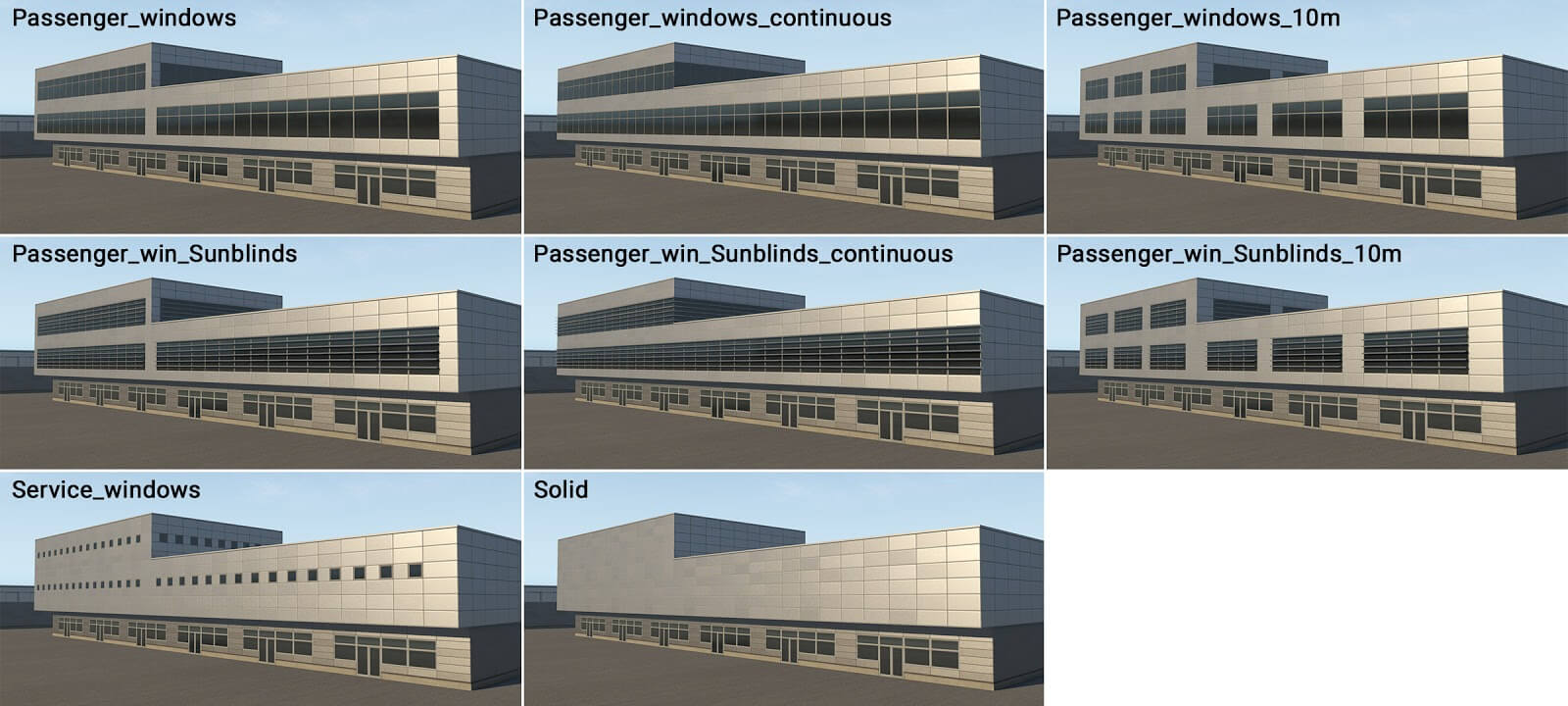
term_building_Levels_02.fac
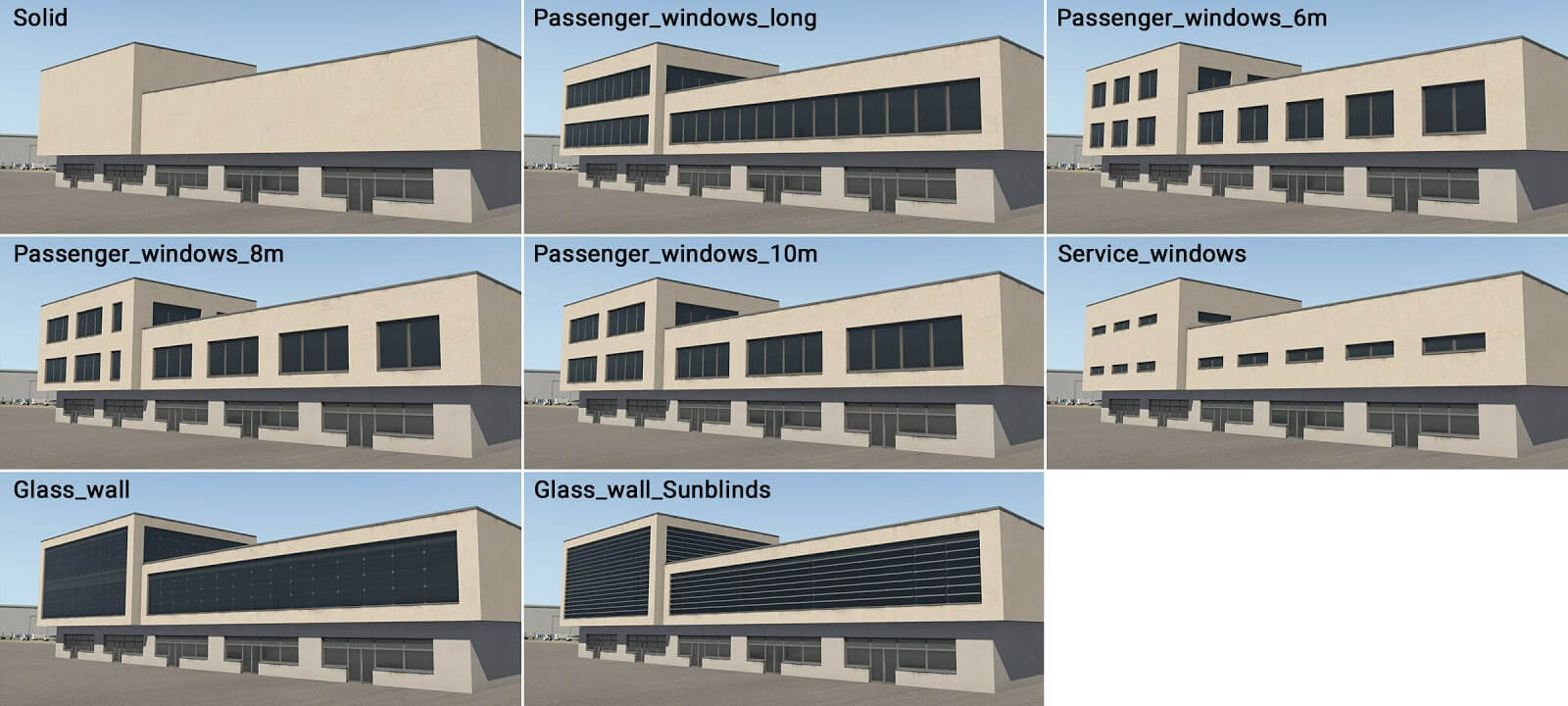
term_building_Levels_03.fac
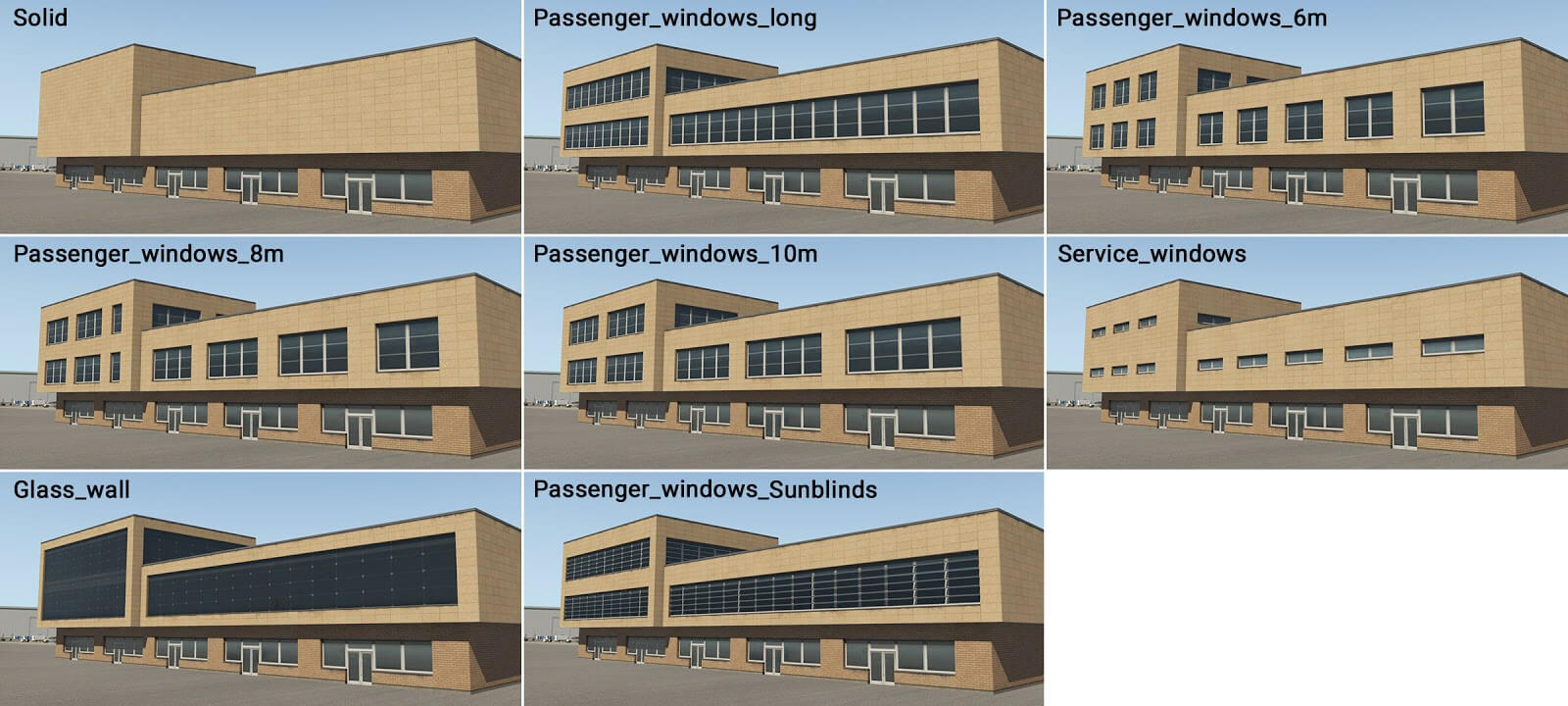
term_building_Levels_04.fac
This module also has one very specific usage: When the height is set at 5 meters above ground-level, this component is rendered as a ‘slab’ (no matter which wall type is selected). This can act as a flat roof, and may be used above the ground floor, or with columns (described later). However in this case it is technically higher than a normal floor (6 meters) so artists may not place roof elements on it. Here is an example:

term_building_Tall_XX.fac
This module has various purposes: volume extensions, stair-towers and other vertical parts. It is slightly higher (by units of 1 meter) than adjacent modules, and can be inserted into other basic modules, or used as a stand-alone module.
term_building_Tall_01.fac
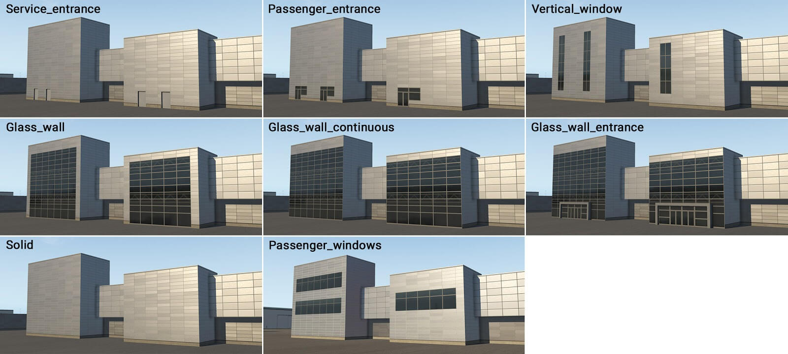
term_building_Tall_02.fac

term_building_Tall_03.fac

term_building_Tall_04.fac

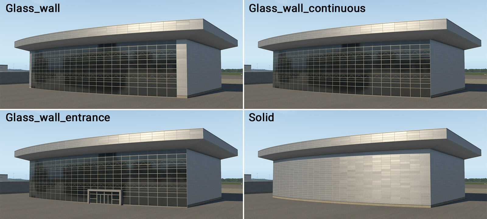
term_building_BigHall_01.fac
This is special module for the creation of large halls with glass walls. It is intended for simple shapes like rectangles, and can’t handle negative corners (concave angles).
term_building_Slab_01-03.fac
This is another special module for the creation of simple slabs. It is available in three different roof colors, each with five edge-material options. It is also compatible with all roof elements, just like “ _Ground ” module.

term_bridge_…
term_bridge_XX.fac
This module is used to create bridges. Technically it is similar in construction to the “ _Levels ” module, but makes only a single floor. If the artist needs two bridges above each other, this is achieved by duplicating the structure at different heights above ground.
term_bridge_01.fac
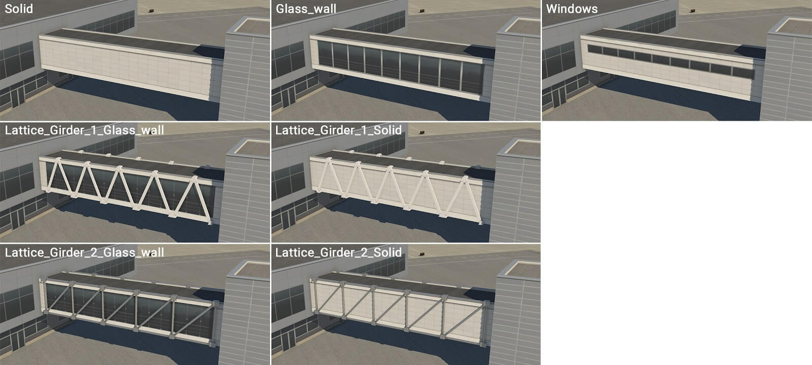
term_bridge_02.fac

term_bridge_03.fac

term_bridge_04.fac

term_bridge_joint_XX.fac
This module is similar to term_bridge_XX.fac , but with a more substantial appearance, supporting just two wall-types – solid, and (very simple) windows. The main usage will likely be situations where two bridge sections are joined together. However, this module may also be used as a second floor, above a ground floor structure.
term_bridge_joint_01.fac

term_bridge_joint_02.fac

term_bridge_joint_03.fac

term_bridge_joint_04.fac

term_roof_…
term_roof_level_XX.fac
This module provides for the creation of roof-superstructures. The module is 3 meters in height, and this is the exception mentioned earlier. The absolute height of this facade must therefore be 8, 13, 18, 23 or 28 meters (as opposed to 5, 10, 15, 20 and 25 meters).
term_roof_Level_01.fac
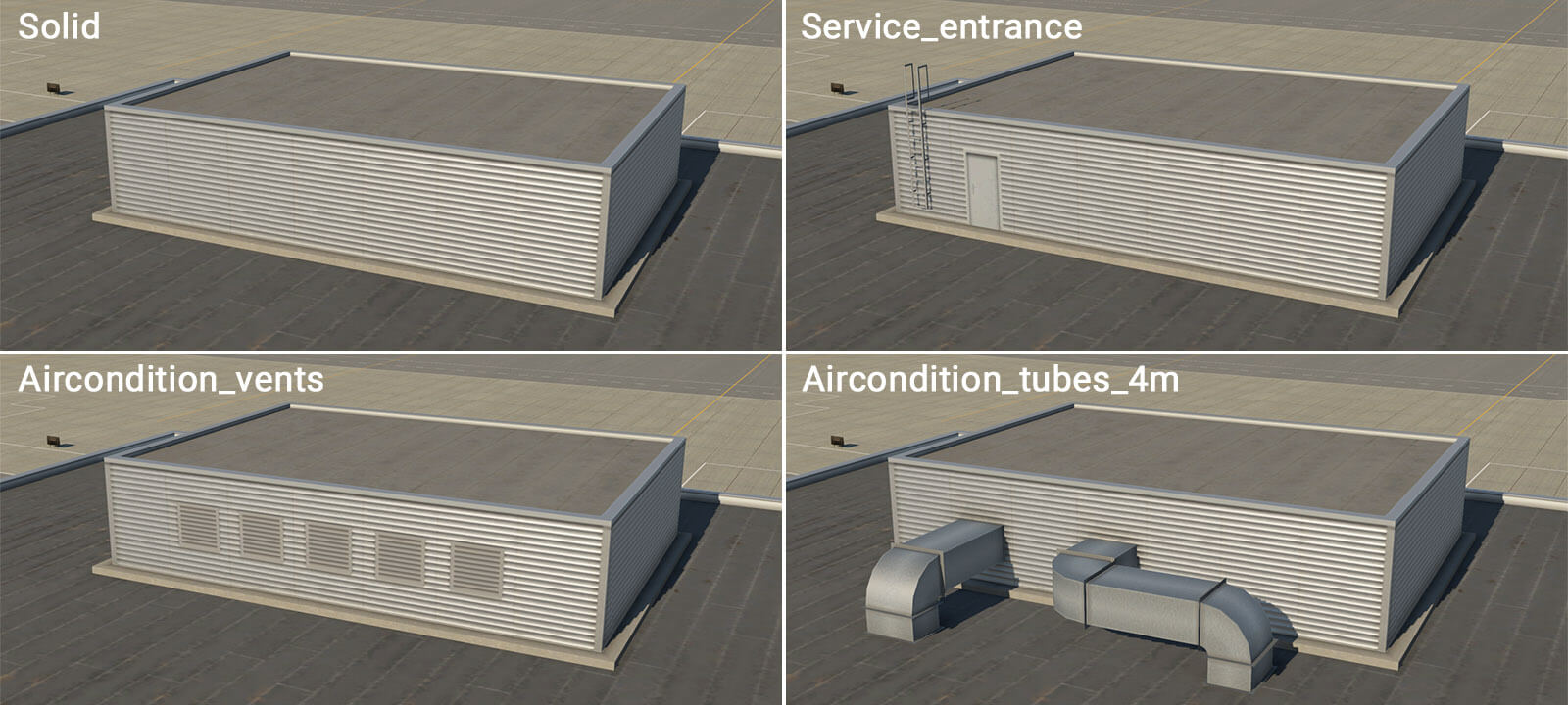
term_roof_Level_02.fac
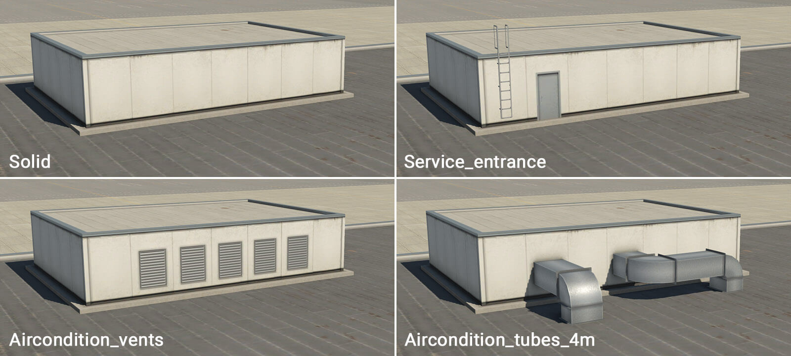
term_roof_Level_03.fac
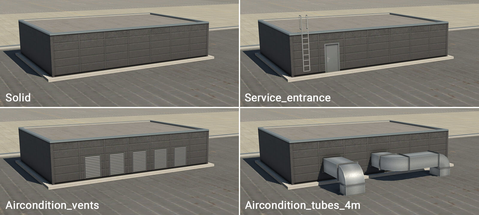
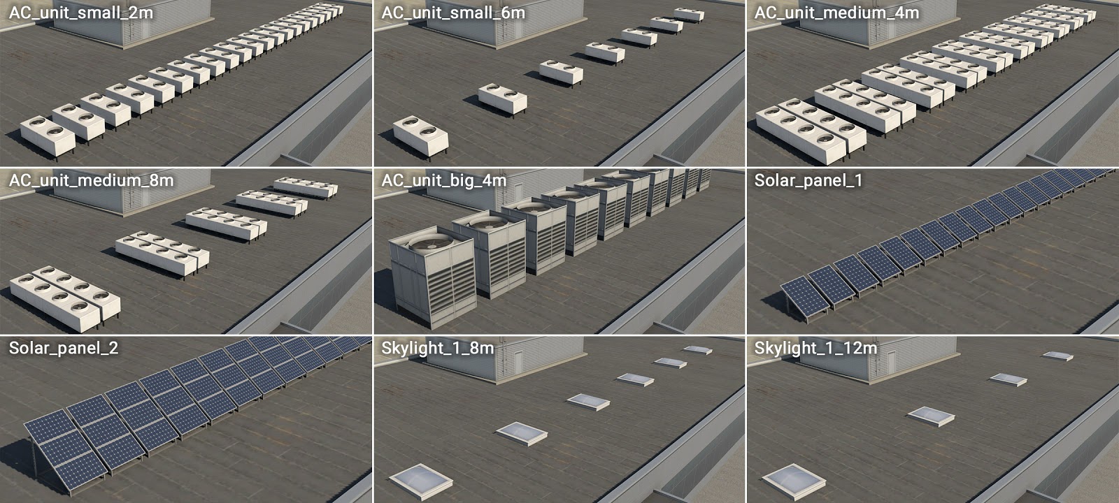
term_roof_elements_01.fac
This is very special module. Technically it has invisible walls and roof, and therefore only the attached objects are visible. This module may be used to support various roof elements, like air conditioners, solar panels or small skylights. This module’s facade isn’t ‘closed’, so artists will see a chain of linear-segments in WED. Attached objects are placed at the center of these line-segments.
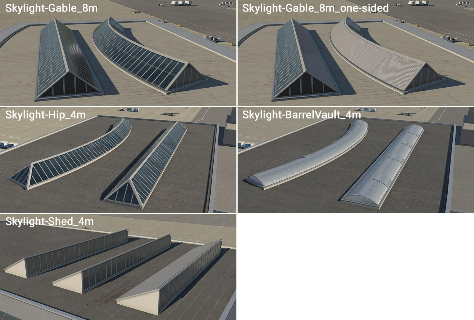
term_roof_long_skylight_01.fac
This is another specific module that forms various longitudinal skylights. This behaves like other WED linear-features, with the line (or chain of lines) itself representing the axis of the skylight.
term_roof_pipes_01.fac
The same principle applies here as to the skylights module, except this module is not limited by one segment. The artist may draw any number of segments in a chain. The basic facade wall generates horizontal pipes which can be connected to another module, such as “ _roof_level “. However, there are also special walls with a “ _start ” prefix, and “ _end ” suffix. This is useful when pipes project vertically from a roof. The direction of the polygonal chain in WED is important here, and this is why the artist must define start and end segments for the facade.


Other objects
There are other useful objects that can be placed manually:
Entrances
Some facades already have walls called “ _entrance ” but sometimes it will be useful to place them manually. Moreover entrances are generic, and can be used with various facades as needed.
Columns
Additional important objects are columns, and separate ground-floor and upper-floor columns are available. Columns are placed manually where required, to form a plausible structure. Columns are available in two lengths – 4 and 9 meters. Shorter columns may be used under “ term_building_Levels ” facade and under “ term_bridge ” and “ term_bridge_joint ” modules (with a height of 10 meters at the lowest position). Higher columns can be used under bridges or joints (with a height of 15 meters at the lowest position).

Useful hints
-This Terminal Facade kit comprises basic modules of 2-meters in horizontal length. This means that a single metal panel is two meters long. There is no explicit reason to be aware of this, except that it may prove useful when positioning manually placed assets (eg entrances and columns) adjacent to the terminal modules themselves.
-All roof textures have some kind of directionality (appearing as ‘strips’). This is always perpendicular to the FIRST segment of the polygon (the white line in WED). You can rotate segments in WED by pressing Ctrl+R. This is important (especially with bridges) whereby the first segment should be oriented in the direction of the bridge axis.
-Large terminal buildings often have a very complex footprint. Don’t attempt to replicate this complex shape with just a single facade polygon. It’s much better to divide the structure into smaller logical shapes. This also helps when dealing with roof directionality, and where there are large differences in terrain elevation at the extreme ends of the building.

-At times, the terrain may have a significant gradient. This may cause roof elements to ‘float’ above the module below, or sink into it. This is because modules are rendered at the exact height of the center of the first polygon segment. To control for this, some roof modules have an “empty” wall. The artist may start the module chain with an “empty” segment, near the center of the first segment of the underlying module. The artist then draws the second empty segment in the desired location of the (visible) roof element, and this should render at the correct height.

-When an artist requires doors, gates or corridors at exact locations in a long module wall, this may be accomplished by the insertion of a node, and a change in wall-type (even in straight segments). Keep in mind that basic modules are 2 meters in length, so try to use segments that are approximately 2, 4, 6 or 8 meters long. This helps avoid unwanted stretching.

-The height of one metal panel isn’t technically one meter, but actually 96 centimeters. The reason for this is related to jetways, but not important to artists when constructing the terminal modules. Likewise, the exact height of floors are actually 4.6 m, 9.4 m, 14.2 m, 19 m and 23.8 m.
I have applied this to the main terminal building for Southend, EGMC which I will be posting to the gateway soon. Having played with this for a day, I think this is a great way of building with facades and would be fantastic to see this feature grow. It is a very powerful tool. thanks for a great explanation.
Will it always be limited to the laminar library, or can developers look to create facades for this new way of working too?
Yes, the gateway is restricted to art that ships with the sim.
This is fun, Are there more additions to the kit planed?
very nice
great to see you expending this concept.
I made good use of these on southend EGMC airport.
Once you get the idea they are a much more powerful tool for multi-story buildings.
I know it’s not really to do with this but is there a chance stand number markers will be added? As someone that on online networks this really would be an amazing feature for default scenery. All the info required is shown on the map, be great to bring it into the sim
When placing windows on the building façade, is the script for the desired window, to be typed into the resource name of the structure? I’m not seeing individual selections containing wall and window types.
Select individual nodes in the terminal shape to see the options to pick the wall type in the attributes pane.
Which node changes which side? I have to go back and forth from the sim to the editor to view my changes, and sometimes they don’t appear to change at all or only some sides change. thanks in advance.
If there appear to be problems with the kit you should file a bug report here.
term_building_slab is still not present in 1.7.0 or am I missing something?
Check that you are using 11.20 beta. The new additions are not in X-Plane 11.11.
Hello the kit is great, but I only have the series 01 of the terminal elements. Where can I get the 02, 03 and 04 series.
Also would be great if you include one facade for doing sidewalks.
Cheers and keep the great job!
Check that you are using 11.20 beta. The new additions are not in X-Plane 11.11.
This is an amazing feature! I am just trying it out at NZDN, however I only have the term_building_Ground_01 kit available (the grey one). NZDN has white terminal buildings so I was hoping to use term_building_Ground_02. Am I missing something or will the other textures implemented at a later stage? Thanks!
Check that you are using 11.20 beta. The new additions are not in X-Plane 11.11.
Hi! This is an amazing tool and I love working with it. I have one question though. In WED I can only see the “term_building_Ground_01” and none of the other styles. I would need a white wall set as shown in “term_building_Ground_02”. Am I missing something or will the other art styles added at a later date?
Many thanks
Stefan
Check that you are using 11.20 beta. The new additions are not in X-Plane 11.11.
Why does my WED version 1.6.1r1 Library Pane only list Terminal Kit building styles in (_01). How do I access _02, _03 and _04 facades shown in the above Terminal Kit Components section? Thanks
Additional information regarding previous inquiry: I am operating with X-Plane Version 11.11
The variants are included in X-Plane 11.20 beta. The article has now been updated to indicate that.
Ben,
The extended Terminal_kit with new textures 2-3-4 became available with XP11 20b3, right?
So, if I made an airport with this updated lib, users with XP11 but no betas will have errors, right? They need XP11 20b3?
Freddy De Pues,
NAPS sceneries
Yes, trying to use newer features in an older version will cause errors. The new variants are only available in 11.20.
Thank you Jen. So a XP11 20 regular will do.
Jennifer,
You programmed the ground level structures to be set at certain heights, this is very useful for creating walls, you know, like the walls surrounding a property for privacy, security or protection. Could we have more textures? Can we induce them?
Question re marking a specific section as say “Service windows”. Using only the available term building Ground Level 1 in XP11.11.
I had a small wall and marked the first node as the above, then at the next node I changed it to solid. However, when the building appeared in XP11.12 the Service Window appeared as a Service Entrance / Tunnel. Is the Kitcnot fully functional in XP11.11 with available .fac?
Fantastic update! This puts airport design on another level. However, because you can create buildings with different levels and different heights, it would be interesting to see in 3D (in a small window) the building that we are creating.
Keep up all the good work!
My base level structure is uneven and not level (appears sinking into the ground). What is causing this and how can I remedy this issue?
Amazing stuff! This is a major ok improvement. Thanks for all the hard work.
Apart from an obvious hope for much more variety of lego pieces in future would you plan to add a roof elements that would work with term_building_Tall_* objects? Currently it is impossible to add pipes to a tall roof (20m+) since they sink due to 1m per level difference.
Will Laminar be providing vertical circular windows for use in terminal facades? I am presently building Albany International Airport (KALB). It’s main terminal has a brick facade but with circular windows. Also the terminal’s gate side has virtical blue panel facade. If you view the airport in Google Earth you will get a better idea as to what I am suggesting. This airport is a challenge because at this time Laminar lacks the ability to provide an accurate reproduction of this airport’s main terminal.
I would like to provide the finished airport to the gateway site but at present I must learn Blender to accurately render the terminal and therefore the airport would not qualify to be uploaded.
R Thomas
I am really enjoying the term kit. Please keep me updated as to upgrades. I am busy with correcting, using Gateway guidelines, existing airports in my region. As well I am working on a few airports that no one has done. Is there a current list of default airports that have not been done? This would help me to choose future new projects. I am a big fan of Mr. Vogel and have learned to emulate his methods. My congrats to the entire x-plane dev team for this product. You have made this retired real-world pilot a very happy person. I plan to share my designs once I am satisfied with the work.
Are artists allowed to use this kit in commercial use (i.e. payware)?
Commercial artists can reference the kit in WED. They are not allowed to copy the .png files and .fac files for other uses.
So artists can use the laminar lib library in payware airports for X Plane 11?
can artists use laminar lib objects etc in payware sceneries ?
Good morning, I’m having trouble using term_ground_01 and term_levels_01 on a concourse I’m building. The first concourse they worked great, but in this one, the second “floor” level doesn’t appear to settle in place and appears high, therefore my wall mounts for jetgates appear low and don’t match the height. Any quick solutions I may have missed? I’ve tried a few things. Thanks 😀
When drawing the polygon defining the facade shape, the first segment you draw is considered the “anchor” segment and is shown with a white line along with the colored wall type line. This anchor segment is used for the height reference. If you have the anchor on the “levels” polygon on a different edge than the anchor on the “ground” polygon and the terrain is even slightly uneven, the reference height will be different and you’ll get this floating effect. Set the anchor segment to the same side for each layer and it should bring the two levels back together. You can use -R to rotate the polygon which also rotates the anchor segment so that you don’t have to redraw the polygon.
Such an awesome addition just figured out i can give my airport solar panels on the ground by setting the elevation to 0m
When drawing the polygon defining the facade shape, the first segment you draw is considered the “anchor” segment and is shown with a white line along with the colored wall type line. This anchor segment is used for the height reference. If you have the anchor on the “levels” polygon on a different edge than the anchor on the “ground” polygon and the terrain is even slightly uneven, the reference height will be different and you’ll get this floating effect. Set the anchor segment to the same side for each layer and it should bring the two levels back together. You can use -R to rotate the polygon which also rotates the anchor segment so that you don’t have to redraw the polygon.
term_building_Slab_01-03
term_building_Slab_01-03 should be allowed to go up, just like bridge and bridge joint.
I agree. A minor change to a facade that would greatly expand it’s use.
In a future update is it possible to give us more flexibility with the floor heights?
For instance if I could raise the floor of a Levels_02 facade I could more easily use it to modify a freight dock. Currently I have to mess with the mesh to get the trailers to fit under it. It would really make it easier to when terrain is causing alignment issues.
But thank you for expanding on this feature!
I am really enjoing creating my custom airport scenery with this. Thank you.
Two things I would like to see in future updates:
1. Have _Ground and _Levels with the same texture option.
2. Be able to place term_building_slab higher at 10m, currently limited to 5m (to create higher larger under roof areas with the 9m columns)
Hi.
Is it possible to create arched hangar roofs with current facades? I’m creating some interior airports (don’t know how to call those small airports in viciny cities) in Brazil and most of them has arched roofs.
Not yet, may be coming i hear
This is great and a quick way of getting good approximate buildings to the real thing without having to struggle with blender o other apps.
But I have a problem: I made a bridge, that is quite long. The original one has a row of columns below to support it (the bridge is set to a height of 15 m.)
I put a row of columns below… but they are short (about 4.5 m or 5). The text says that below bridges we can use taller columns up to 15 m. But it seems there is no way to set the column height… am I loosing something?
How is it suposed we do to get taller columns when we need them?
TVMIA.
Hello i wonder if we can use laminar library objects (grass,cars,forests airport objects vor ndb windsock etc) thanks