X-Plane 12 can simulate both rain drop/wiper visual effects as well as icing and window heat effects on aircraft window surfaces. This article explains how to implement and calibrate rain effects only. Icing effects are discussed in its own dedicated article, “Windshield Ice Effects”. This article assumes you are familiar with:
- Blender / 3D / keyframing
- X-Plane 3D objects (*.OBJ files )
- UV layouts
- face normals
- RGBA image channels
- xplane2blender / UI locations
Rain Effects General Information
- The 3D OBJs to receive rain effects should only contain polygons for surfaces with rain effects. Do not include opaque or non-rain-effects polygons as part of your rain-glass objects.
- You should expect to use two separate OBJs to represent your rain glass: one OBJ with outward facing normals and another OBJ with inward (cockpit/cabin) facing normals. Best practice is to name these two OBJs as follows for clarity reasons:
<aircraftName>_outside_rain_glass.obj
<aircraftName>_inside_reflector.obj
- Each individual window should to be a continuous, manifold mesh in 3D with no UV seams, so that when UV unwrapped, the resulting UV island mesh is also continuous. Do not split up a singular window into multiple UV islands.
- No UV island of any one window should overlap another on the texture. UV islands should have consistent texel densities between them and minimal warping for consistent rain drop sizes.
- Any transparent meshes inside the aircraft, (typically translucent sun-visors) where you need to see the rain effects through these meshes, should be part of the inside_reflector object; however, the draw-order of the meshes within that OBJ may need to be configured (more below).
- While you CAN use multiple OBJs set to Outside Rain Glass, this is not recommended. You should endeavor to use one OBJ for all external glass with rain effects and a second OBJ for all the inside (reflector) facing glass.
Enabling Rain Effects on OBJs
Rain effects can be enabled on your window OBJs by setting their lighting mode in PlaneMaker to either Outside Rain Glass or Inside Reflector. Use Outside Rain Glass for your OBJ with outward facing normals and use Inside Reflector for any windows (or visors) with inside/cockpit/cabin facing normals.
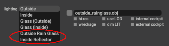
These two OBJ lighting settings are complementary and intended to be used together. If not utilized together, then inconsistent rain effects in various X-Plane views may result. X-Plane will simulate raindrops on these OBJ meshes, including the effects of gravity and aerodynamic forces.
UV Considerations for Rain Glass
To avoid differing raindrop sizes on your individual windows, ensure that the texel density of your UV islands are consistent.
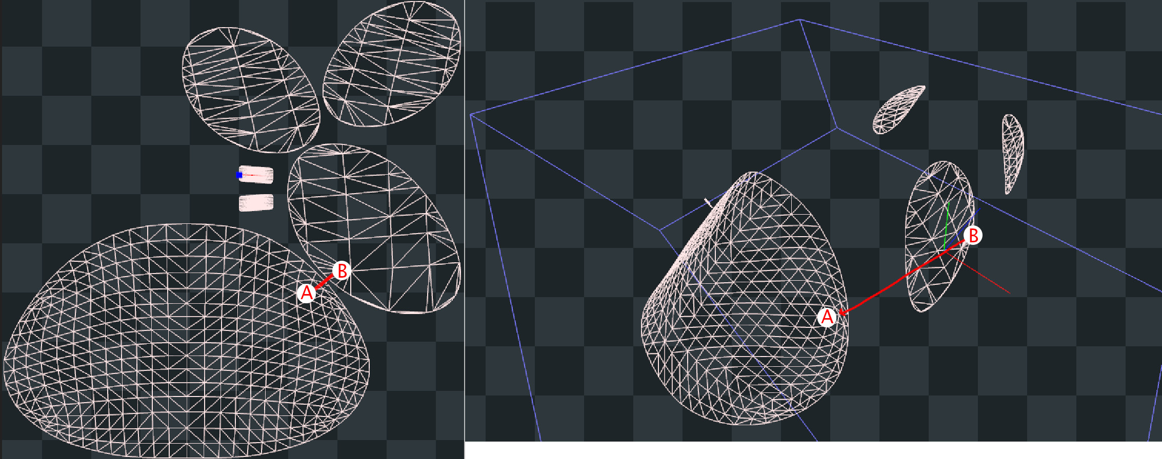
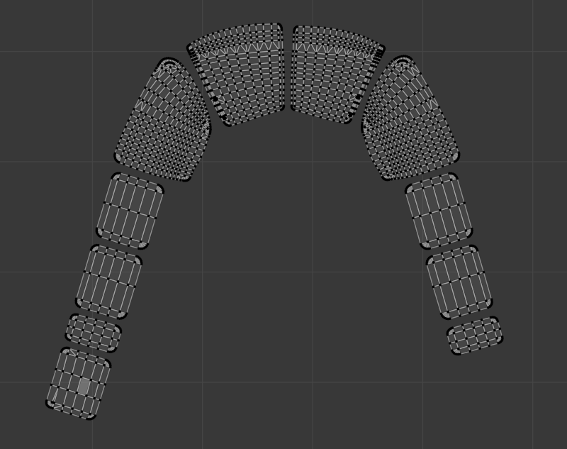
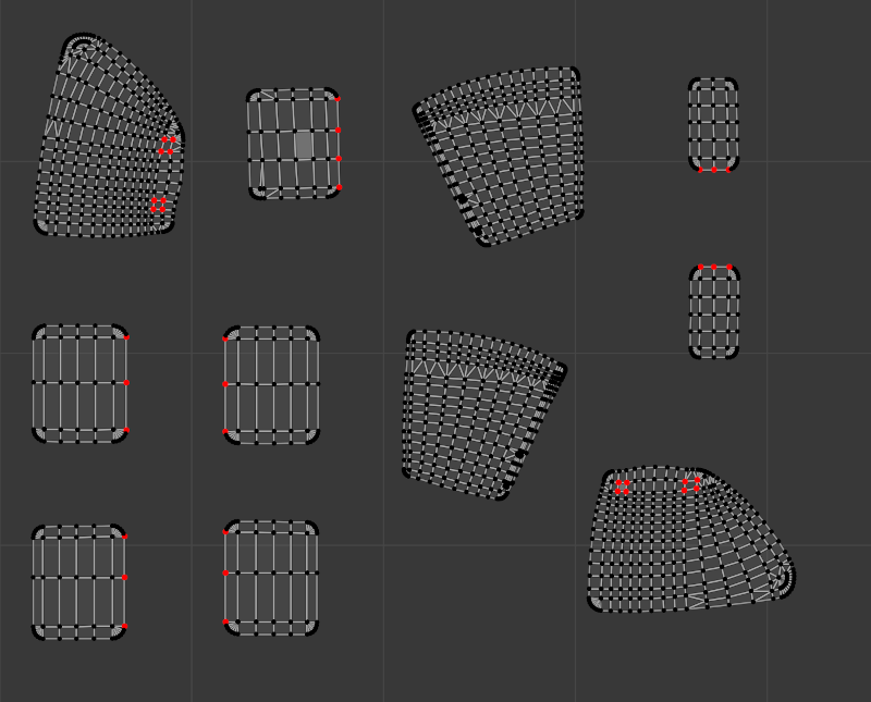
Regarding UV island packing, each flight loop, the rain algorithm calculates the velocity, direction and momentum of the raindrop in 3D space and then animates its translation on the 2D texture accordingly for the next flight loop. The algorithm knows when a raindrop is within the bounds of a UV island, so when a raindrop has been calculated to move outside of any UV island, then the raindrop ceases to exist. If your UV islands are packed close enough together, then the speed and momentum of the raindrop may be enough where the raindrop “jumps” from one UV island to an adjacent one in 2D space during one flight loop calculation. This effect is illustrated in the screenshots below on the default Lancair Evolution.
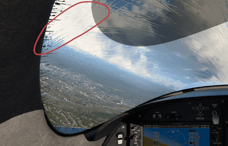
On the UV map (left side), the window uv islands are placed very close together, but the physical 3D locations of the window elements (right side) are not that close together, so in reality, a raindrop would not instantly jump from point A to point B as shown below, yet because the UV islands are close together, the algorithm may animate the raindrop as if this is what happened. If your UV islands are not aligned in a natural way, then a “jumping” raindrop could appear to change directions as its momentum carries it into the adjacent UV island, but with the direction vector from the previous UV island. The red circle in the image further below shows the undesired result of such a situation.
There are three ways to avoid this unwanted effect:
1. Use TRIS_break Directive (12.1+ only)
This is the preferred method for projects supporting X-Plane 12.1+ only. It allows for maximum UV island packing efficiency. If using this method, then each individual window should be separated to be its own mesh object in Blender. If using XPlane2Blender V4.3+, then on each window mesh, enable the “Rain Cannot Escape” checkbox_**.**_ The TRIS_break directive will then be applied to each window mesh. The image below shows the checkbox option and the typical results in the OBJ file.
The TRIS_break directive is a ‘separator’ between TRIS commands and does not need to exist both before and after a TRIS entry in the OBJ file; however, Xplane2Blender may put extra TRIS_break directives before and after some TRIS commands, which is fine. If you are manually editing the OBJ file, just know that a single entry between your rain glass TRIS is all that is required to prevent ‘raindrop jumping’ between those TRIS groups.

2. Align UVs in a Natural Way
If you want to pack your UV islands tight, get good visual results, and still support X-Plane versions prior to 12.1, then you can align your UV islands so that if a raindrop is moving fast enough that it migrates from one UV island to the next in a single flight loop, then it will be moving in a consistent direction between the UV islands. The example below shows how such UV islands might be aligned. If using this method, then each window does not need to be separated into its own mesh object, all windows can be part of a single Blender mesh object. This method is not recommended for large rainglass texture sizes! as it wastes too much textures space and VRAM. The better solution for pre 12.1 rainglass support is to pack your UV islands just tight enough to avoid raindrop “jumps” (method 3 below)
3. Spread out your UV Islands
The third option is to spread out your UV islands as required, orienting each island any way you like as long as they’re just far enough apart where a raindrop is unlikely to translate from one UV island to another in one flight loop calculation. As raindrops move outside a UV island, they cease to exist. Again, this method wastes some texture space similar to method 2 above, but not as much. As with option 2 though, the windows do not need to be separated into their own mesh objects. This is the better method if you want to support XP version before 12.1.
Windshield Friction (12.1+ only)
Different windshields might have different coatings applied to them to affect how rain interacts with them. For example, on aircraft with blowers, the windshield tends to be coated with a highly rain repellant material to avoid rain drops accumulating or streaking over them. Likewise, some aircraft also have the option to apply rain repellant during the flight to decrease glass friction. Starting with X-Plane 12.1.0, this can be modelled using the following GLOBAL directive in the OBJ header section.
RAIN_friction <some/dataref/and/default_is_1>
The dataref lets you adjust the friction dynamically at runtime, although most aircraft will probably just use a fixed value as this is not a common option on aircraft glass. Decreasing the value will decrease glass friction and also decrease the likelihood of rain drops becoming streaks.
Rain Drop Size / Scale
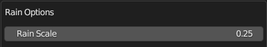
X-Plane creates rain drops with a default, unitless size of “1” and depending on the texel resolution of your UV islands, the rain drops may need to be scaled up or down for your application to look more plausible. The scale of the raindrops may be altered to be bigger or smaller via an OBJ Global Directive, “RAIN_scale”. This scaling factor can be set via the Collection Properties Panel. This value is typically set after testing in X-Plane using the Rain Inspector Tool described next.
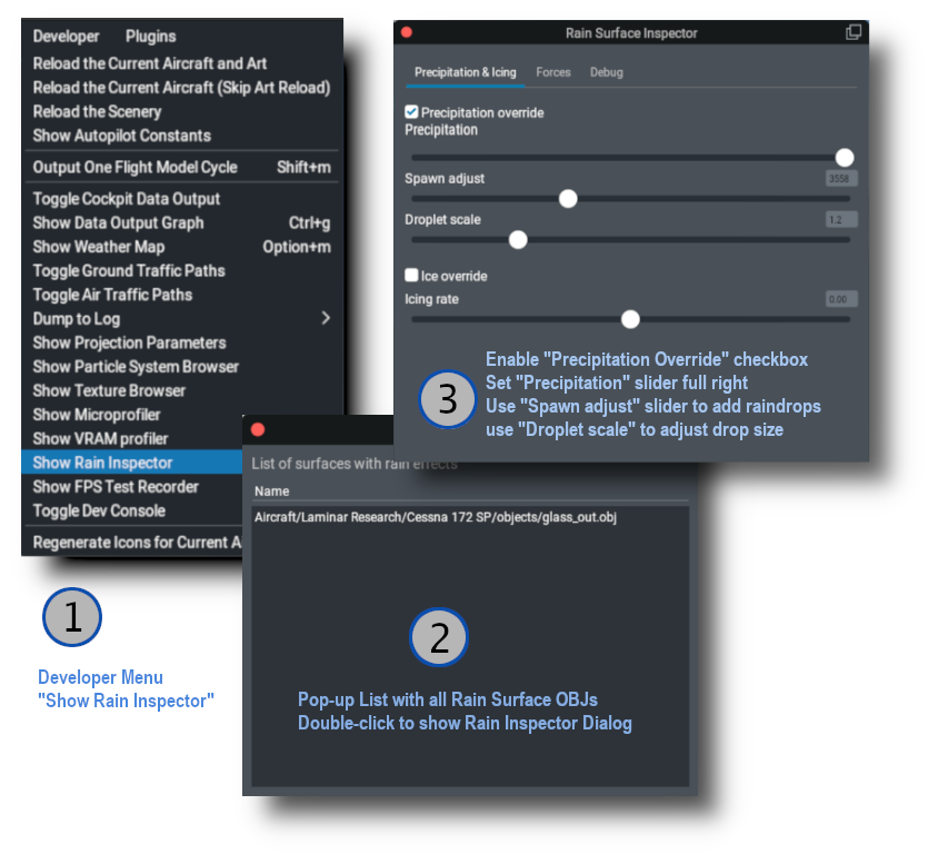
Rain Inspector Tool
X-Plane has a tool to debug Rain Effects in sim. This tool was developed for internal Laminar use but proved useful enough to make available to the public. Being an internal tool, it has several settings you will not need to be concerned with. This tool allows for quick testing of the rain effects without having to change X-Plane’s weather settings. The image below shows the sequence for use. If you have configured your OBJs to be rain glass/inside_reflector, you will see the rain effects in X-Plane as you make adjustments to the Spawn and Scale sliders. Note that its typical to run your test on the Outside Rain Glass OBJ only since that is the only surface exposed to the rain.
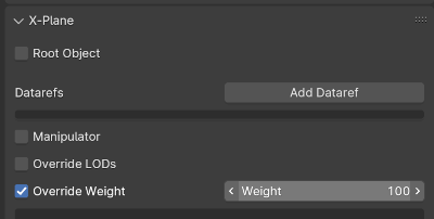
Be sure you check the rain effects from both inside and outside the aircraft. If you have any translucent sun visors, then make sure you can see raindrops through those as well. If you cannot, then make sure your sun-visor meshes are part of your Inside reflector OBJ and also that your sun-visor meshes have been configured to draw last within the OBJ by using XPlane2Blender’s “override weight” option on the object property Tab as shown below. Mesh objects assigned a weight value will draw in the order of their Weight values, with the highest weight value mesh objects drawing last.
3D Windshield Wiper Effects
If your aircraft have 3D windshield wipers, you will first need to configure the periodic timing of the wipers in PlaneMaker via the Standard Menu > Viewpoint > Cockpit Tab > Wipers panel as shown in the example screenshot below.
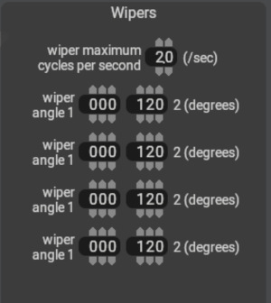
In this panel, you specify the limit angles of the wiper travel (usually 0º to some max valueº) and their oscillation frequency. These fields establish the range of values of the four wiper angle datarefs below, which can be used to drive your 3D wiper animations as well as the 2D wiper effects.
// Dataref to turn on the wipers
sim/cockpit2/switches/wiper_speed_switch    // 0 = park,    1 = 25%speed,   2 = 50%speed,    3 = 100%speed.

// Datarefs for the Instantaneous Angle of the wiper arms
sim/flightmodel2/misc/wiper_angle_deg[0]
sim/flightmodel2/misc/wiper_angle_deg[1]
sim/flightmodel2/misc/wiper_angle_deg[2]
sim/flightmodel2/misc/wiper_angle_deg[3]
Since the raindrop animations happen in 2D texture space, and windshield wiper animations exist separately in 3D space, then we need a way for the 2D rain algorithm to know where your 3D wiper blades are on the window so the effects are in sync. You don’t want the 2D rain wiper algorithm wiping away raindrops behind or ahead of your 3D wiper blade, so timing the 2D effect with your 3D animation is critical.
The 2D wiper position reconciles with the 3D position through the use of a dedicated “wiper gradient texture”, with colored gradient regions that represent the area swept by the 3D wiper blades across the UV islands. The color black represents one extreme position of your wiper travel (0% / wiper angle 1) and a fully saturated color channel (100% red / green / blue / alpha(white)) represents the other extreme position of your wiper travel (wiper angle 2). The example below shows how these swept gradient regions overlay the UV islands of windows as well as how the gradient values represents wiper travel.
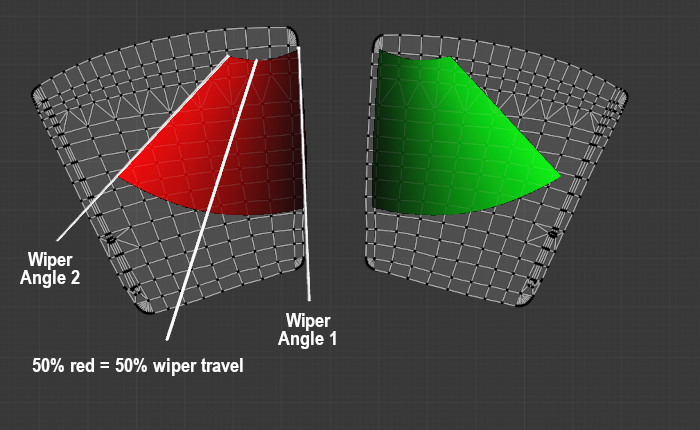
Because we use a single image with four channels (RGBA) to contain the wiper data, this means we can simulate up to four independently controlled wiper blades per OBJ, but most of the time there’s just one or two. The image below shows what a typical wiper texture looks like for two independently controlled wipers where RED = wiper 1, GREEN = wiper 2. (BLUE = wiper 3, Alpha = Wiper 4, neither of which are used below). Note that if both wipers were controlled together by a single dataref (wiper 1), then both wiper gradients would be RED.

If your windshield wiper animation is completely linear, i.e. you only have two keyframes at the extreme positions, then the gradient texture would also be completely linear along its arc and you might could paint this texture by hand with some deft software ninja skills, but its not always as easy as it may appear and getting the gradient exactly right so the wiper effect matches the 3D wiper position can be a challenge. Fortunately, XPlane2Blender has a solution for us! The “Bake Wiper Gradient Texture” tool.
Wiper Gradient Texture Baking
This tool will automatically create your Gradient Wiper Texture for you by using your 3d animation to generate the 2D wiper texture. In general, you’ll create a temporary ‘baking texture’, input/set multiple parameters in Blender, begin the bake, and during the bake process, the script will create a temporary folder and bake 255 temporary images per wiper. After that baking step, the script will then use those temporary images to create the final wiper texture, save it and delete the temporary folder. The baking process can take a while depending upon your machine capabilities, bake settings and texel densities. The single wiper example shown below was done on a Mac M1 laptop and took approximately 12 minutes total with a conservative texel density. Higher texel densities will increase bake times.
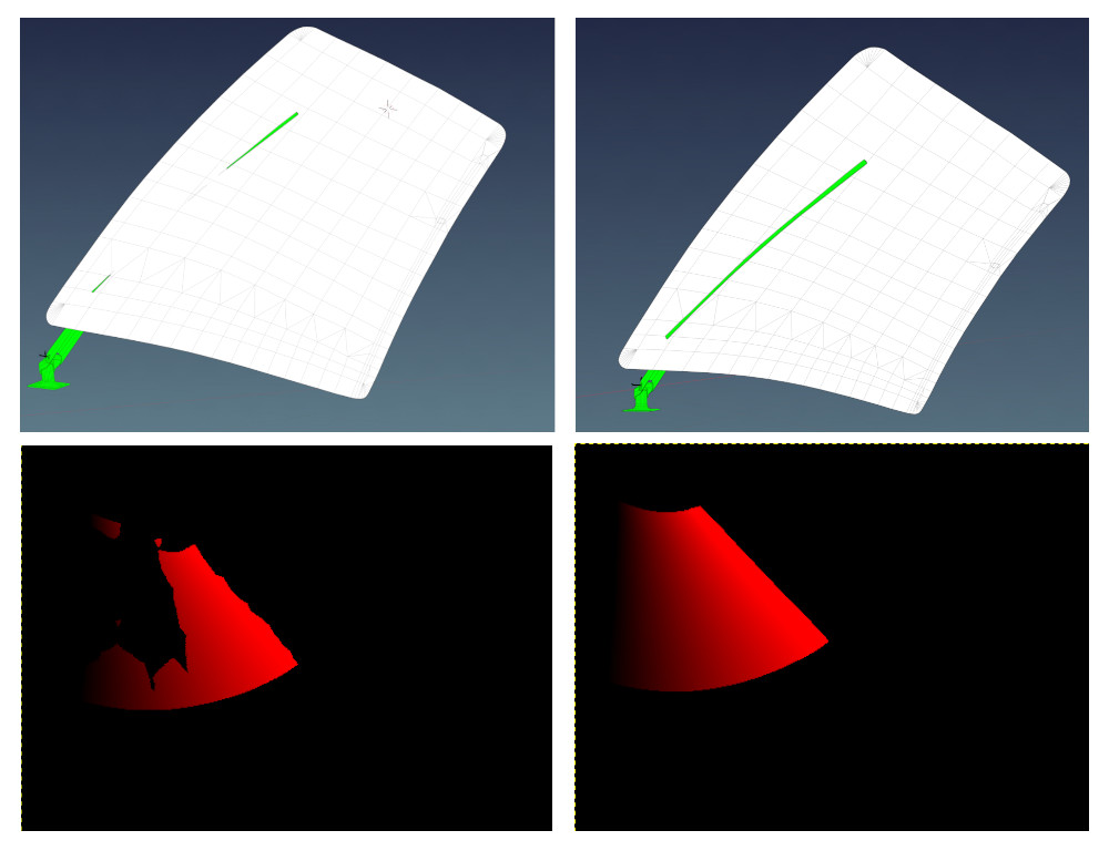
💡 IMPORTANT: For usable results, the wiper blade and windshield need to be in “collision contact” throughout the animation, i.e. the blade penetrates THROUGH the windshield mesh. If not, you may end up with areas on the UV island that are not calculated properly and you will get blotchy results. The image below shows the difference in results with partial intersecting geometry (left side) vs. fully intersecting geometry (right side). Its common to duplicate a blade temporarily and reshape / extend it through the windshield just for the gradient bake and then discard it after.
There’s a lot of steps in the baking process, so we’ll just dive right in via a step-by-step checklist:
-
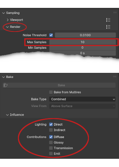
Make sure ‘Cycles’ is the active renderer. It will not work with Eevee or Workbench.
-
Set your Cycles Render samples (not Viewport) to a low number, like 10, and set your Lighting and Contributions check boxes as shown below. (Blender 4.1 shown). This will reduce baking time.
-
A four channel (RGBA), 8-bit per channel (32 total) “temporary baking texture” must exist beforehand. Create, name and save an empty PNG the same size as your final texture, any filename will work. If you use Blender’s Image>New menu to create the image, do NOT select the ‘32-bit Float’ checkbox option, this results in 32-bits per channel, not 8 and will prevent the bake.
You can put this temporary texture anywhere you like for the bake, but we recommend putting it in the same location where you normally keep your other OBJ textures because the script will automatically create the final wiper gradient texture in this same location AND automatically enter the file path in the “Wiper Gradient Texture” text field for you (overwriting any existing entry). If you move the wiper gradient texture to some other final location after the bake, you will need to adjust the file path so it gets written to the OBJ header correctly. -
Add an Image Texture Node to your rainglass material, and select the temporary baking texture you created in the previous step. The wiper script leverages Blender’s baking workflow and gets the file path to the baking texture from this image texture node. Unlike a regular Blender bake however, the image texture node need NOT be selected to bake, but does not matter if it is. Below is an example of an image node with the temp baking texture selected.
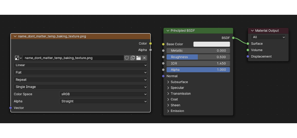
-
Animate your wiper motion over 255 frames (required). You can begin at any keyframe ≥ 1, but your last keyframe needs to be (Begin keyframe + 254). So if you begin your animation at keyframe 1, then your last keyframe will be 255. If you begin at keyframe 16, your last keyframe is 270, etc. The baking UI dialog allows you to specify the first keyframe value and Xplane2Blender will add 254 to it. The default begin keyframe is 1, we recommend you stick with that. You can use as many intermediate keyframes as is required for your animation. TIP: If you have already animated your wipers, but not over 255 frames, then note that Blender’s scale(S) command works on keyframes! Set the animation playhead on your first keyframe, select all keyframes for your wipers, hit ‘S’ and simply scale all your keyframes until the last one is 254 frames after the first one.
-
If you want to bake all wiper regions at the same time, then combine all window mesh objects that have wiper effects into a single mesh object (CTRL-J) for the bake. Give the mesh object (in the outliner) a unique name, e.g. wiper_windows. After the bake, you can separate out the mesh islands if need be, for example if you’re using TRIS_break option on each mesh object. You can also bake each wiper region separately if you want to and combine the images manually, i.e. you need to rebake one window only.
-
To shorten the bake time further, you can separate out the wiper BLADE mesh only (the part that touches the window). The fewer polygons involved in the calculation, the better. Give the wiper mesh objects that intersect the windows unique names (in the outliner) such as:
- right_wiper_blade
- left_wiper_blade
-
Now its time to enter all the pertinent data into the Rain Options panel (Scene Tab Collection Settings). Note that if your “Wiper Texture Gradient” text field is empty (the script will fill it in after the bake), then the wiper UI elements may appear grayed out; however, this is simply visual and you can still enter information in them. You will be manually entering mesh object names (from the outliner) into the Wiper settings text fields. If you misspell the name, the script will let you know with an error pop-up when you try to bake. In the example screenshot below, Item A is the Exterior Glass Object with wiper effects. Item B is a wiper blade mesh and Item C is a second wiper blade mesh. These fields tell the script which mesh objects to include in the baking process. If you have more wiper blades, just enable the bottom checkbox to enter their data. The example below will bake two wiper gradient regions to the RED and GREEN channels of the gradient texture.
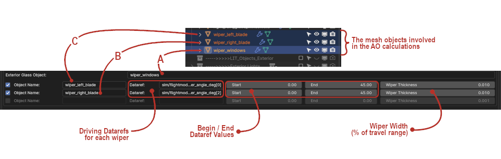
- NOTE: Each time you enable a checkbox, a new one will appear, up to 4 total. In the Object Name text box, enter the name of the Wiper Blade Mesh Object. Confirm name in Outliner. The first wiper will be Wiper 1 (red), the second Wiper 2 (green), etc, etc.
- Enter the name of the driving datarefs for each wiper and keyframe values. This data will get written to the OBJ file. Common datarefs are:
-
The following two items are required in order for the Bake Wiper Texture Gradient button to activate.
- The collection with the rainglass meshes must be enabled for export on Blender’s Scene Tab.
- The collection with the raingless meshes must be selected in the outliner.
-
Time to Bake! On Blender’s Render Properties Tab, and with the above two criteria met, the “Bake Wiper Gradient Texture” button should now be active. Press the button to begin the bake. The image below shows the sequence of the Gradient Texture Baking Process.
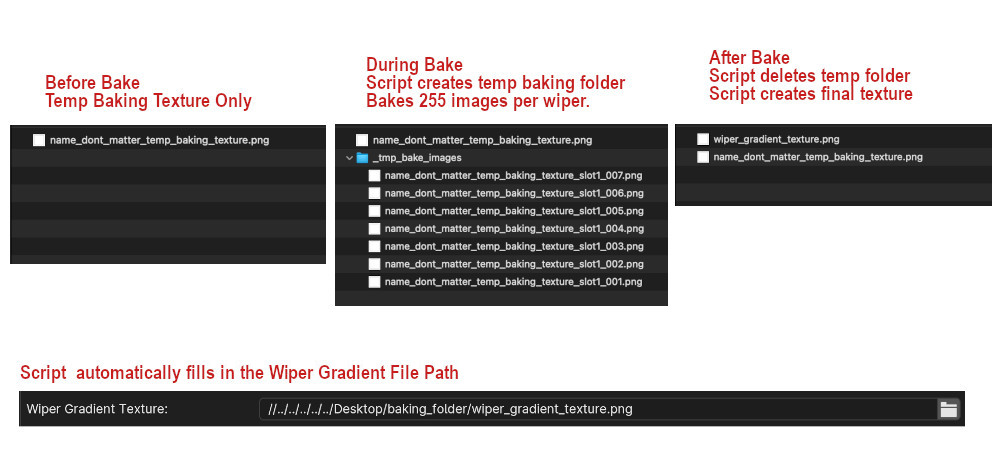
A few things to note about the bake process:
- During the bake, you will not see any animation in the 3D viewport. The wipers will not move. Blender is essentially “frozen” with no progress indicator, so don’t plan on doing any work in Blender while the bake is going on.
- You can monitor the progress by observing the contents of the ‘__tmp_bake_images_’ folder, which will be growing with files as the 255 images (per wiper) are baked. Do expect 10+ minutes per wiper channel.
- Once all images are baked, there will be a period of time with no apparent activity as the script calculates and assembles the final gradient image.
- When complete, the temporary folder will be gone, the “wiper_gradient_texture.png” file will be in the folder and Blender will be functional again.
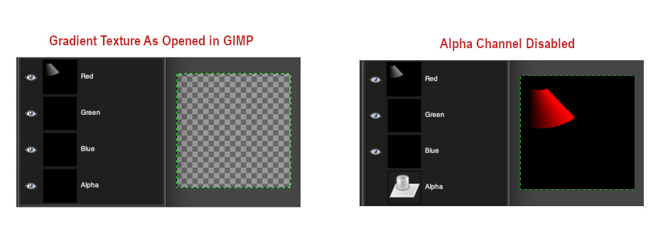
💡 NOTE: The script writes to all four image channels (RGBA) regardless of how many wipers are configured. If baking less than 4 wipers, the alpha channel will be completely black and as such, the RGB channels will be transparent when you open the image; however, the color information for the baked channels is present as can be seen below. Disabling the alpha channel will reveal the RGB channels.
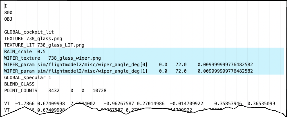
Exporting and GLOBAL Settings
After exporting your rainglass object, the rain settings will be present in the GLOBAL properties of the OBJ as shown below. The default 737 example below has two independently controlled wipers, a custom rain scale and one wiper gradient texture. Remember that the wiper baking script will auto-name the baked texture, “wiper_gradient_texture.png”, but you can rename it to anything you like. If you do rename it, then make sure you also change the filename in XPlane2Blender’s “w_iper gradient texture_” text input box. Its good practice to check the exported OBJ to make sure all the settings and filepath are as expected.