There have been plenty of rumors and semi-official posts regarding the upcoming major revision of X-Plane (X-Plane 9). I have been trying to keep my mouth shut about it…the problem with pre-announcing anything is that the upside to us is small (at best we do what we said) and the downside is large (at worst we don’t do what we said and people get grumpy). No one complains if XP9 turns out to have no-pause scenery load and it’s a surprise…but plenty of people complain if we say “there won’t be pauses” and then they are.
But…the situation is becoming mildly absurd…plenty of info is out there, and saying “the upcoming major release”, etc. just feels political and weaselly. Austin would be disgusted.
So listen: I am going to try to provide some info on X-Plane 9. This info is subject to change. This is what we think is going to happen to the best of our knowledge. The release is still a ways away and enormous changes will happen. When things change, do not bitch to me that “you promised X” would happen. I do not promise anything. This info is provided to try to help those making add-ons for X-Plane plan appropriately.
With that in mind…I will try to post some more details on the authoring environment in the next few days. For now, here’s some very basic guidance on compatibility and hardware requirements:
- The hardware requirements will be at least as high as X-Plane 8. If your machine is gasping and wheezing on 8, it’s not going to be any better on 9.
- X-Plane 9 will depend more heavily on pixel shaders. If your hardware doesn’t have pixel shaders (GeForce 2-4, Radeon 7000-9200) or has really crappy shaders (GeForce FX series) you will miss out on a lot of the cool stuff in v9, and possibly have the scenery look worse (but faster) than v8 (as we move features from the CPU to pixel shaders).
- Scenery that opens in x-plane should open in X-Plane 9 unmodified – if the scenery works in 8 but not 9, report it as a bug!
- Plugins that work in v8 should work in v9 without modification.
Finally, we are trying to finish up X-Plane 861…this is a bug-fix patch for version 8 – it contains no new features, but it does fix a few nasty bugs, some of which cause crashes. So if there is any new feature, it’s coming in 9, not 861. Version 8 has been out for a very long time, so I will accept no argument that v8 should have more features than it does now. It’s been a long run!
(One of my main goals with 861 is to try to fix any weird behavior for third party scenery add-ons, so that a scenery add-on looks the same in v8 and v9. If we left the bug in 861 and fixed it in v9, authors would have to hack the scenery to make it work with v8, and then remove the hack and republish for v9. By trying to fix the authoring bugs in v8, at least when possible, it lets authors publish one package for both versions. Of course, v9 will have new features, so I expect some v9-only scenery will emerge pretty quickly.)
In my previous post I described the underlying problems that make translucency in airplane cockit objects tricky. That gives us the background to understand how X-Plane draws cockpit objects and why.
The actual draw order for airplane-related objects is this:
- Far away weapons.
- All of the airplanes that we are not inside (this means the user’s plane in an external view, and AI planes all the time). For each of these planes, the external cockpit object is drawn first, then the parts, then the attached objects in order.
- Clouds and puffs and other such environmental phenomena.
- The geometry of our plane, if it is to be drawn and we are in an inside view.
- The attached objects in order for our plane, if internal geometry is drawn and we are in an inside view.
- Weapons that are very close to the plane.
- The inside cockpit object, if we are inside the plane.
A few things to note about this draw order:
- Note that weapons appear twice in the category of “near” and “far”. This is all about the clipping plane – if a weapon is close to us, it must be drawn with the cockpit object, late in the draw cycle, when we are doing “close” things. Weapons are treated dynamically – they change where they are in the draw cycle depending on their position in space. This is necessary because a weapon starts out real close (just off your wing) and then goes real far away.
- The user’s airplane is special-cased when we are in an internal view … at that point if external things are being drawn, they are done in the later “close” view with the cockpit.
- The external cockpit object is (strangely) quite early in the draw order. There’s really no good reason for that. What’s particularly annoying is that it’s inconsistent with the internal draw order. The main point of internal/external cockpit objects is to let you simplify your cockpit object in external view for performance.
Is there a sane way to set up an X-Plane 860 aircraft with translucent geometry? I’m not 100% sure about this, but it looks to me from the code like the correct thing to do might be:
- Put any translucent windshield/canopy/etc. in the last attached object.
- Put only the interior panel (and not the canopy) in the cockpit object.
This works because in the external view the canopy is drawn last, and in the internal view, the panel is more or less guaranteed to be closer than the canopy, which is good enough.
Today is Rosh Hashanah, the Jewish New Year. In Jewish tradition it is also thought of as the birthday of the world. If you’re reading this blog, you probably have some interest in how X-Plane attempts to simulate the world on your computer. The attempt over the years to create a higher fidelity simulation has led me to a deeper appreciation of the subtlety, complexity, and beauty of the real thing.
(Nothing makes you realize how rich and intricate the world is than trying to model it with a few million triangles and ending up with something that looks completely crude.)
X-Plane’s digital world isn’t the only way that we interact with a proxy instead of the real thing. When we drive instead of walk, eat packaged food from a supermarket, talk on the telephone instead of talk in person, our technology becomes a proxy for our relationship with our direct natural environment – the planet, plants, animals, and other human beings.
Now I’m not saying that any of these things is bad. I’m not about to become a dairy farmer, and without the internet we couldn’t create X-Plane at all. But I think it’s important on this day, and hopefully every day to take time for activities that put us in direct contact with the world. Consider a few questions:
- How does what I eat affect the world?
- How does my travel affect the world?
- What impact does my home have on the world?
- Am I leaving the world in better condition for the next generation or worse?
Please … take a few moments to consider the world, the only home we’ve ever had.
When I was in the Dolomites a few years ago with Sergio we were looking at the dolomites from his friend’s balcony – mile after mile of beautiful mountains and rolling hills. I looked at him and said “God has more polygons than we do.” It was a joke at the time, but I think that the act of really observing the real world and realizing that the digital reality and technology we create can be a proxy and an addition but never a replacement is critical to understanding the responsibility for stewardship we have over the planet. Are we taking good care of our most precious gift?
Side note: please do not post tech support questions as blog comments – please use the x-plane-scenery yahoo list or the x-plane.org scenery forum. I would like to keep tech support discussions in easily search-able public places so future users can get answers quickly.
I saw a post on x-plane.org referring to the process of creating translucency in objects attached to airplanes as a dark art. There is definitely a lot of weirdness in how X-Plane draws airplane objects. I will try to shed some light on what’s really going on and how to deal with it. For this first post, I’ll explain the requirements of the hardware, which shape the ensuing chaos.
First, and most important, in order for X-Plane to render translucent geometry (objects or otherwise), the geometry must be drawn from farthest from the viewer to closest. This is in stark contrast to normal operation — for transparent or opaque geometry, we can draw the closest objects first, and the graphics card makes sure the far away objects don’t “paint over them”. But the technology that does this (z-buffering) doesn’t work when the closer geometry is translucent. (If the translucent geometry is drawn first, it acts opaque to what is behind it.) For more info on this phenomenon and what to do about it, look here.
So in order for our translucent cockpit objects to draw correctly they need to be drawn from “back to front”. But note that this term is relative to the camera — which object is closest will depend on where the camera is located!
The other cause of cockpit object weirdness is the near clipping plane. At any time when X-Plane is drawing, there are two limits on where we can draw:
- The near clipping plane defines an invisible wall – anything closer to the viewer than this distance will not be drawn.
- The far clipping plane defines the other invisible wall – anything farther from the viewer than this distance will not be drawn.
The far clipping plane is usually set far enough away that objects disappear into the fog before hitting it. The near clipping plane is usually set close enough that by the time an object hits it, your plane has crashed.
Now here’s the rub: the quality with which the graphics card can discriminate which polygon is closer (via z-buffering) goes down as the ratio of the far to near clipping plane gets larger!
Take a second to think about that. Basically if we want to increase the visibility in X-Plane without losing z-buffering fidelity ,we need to move the near clipping plane farther away from the user.
The real problem is this: X-Plane, with its sometimes long visibilities (when you get up into orbit, you can see a long way!!) really stretches the z-buffering fidelity of even modern cards. So we have to keep the near clip plane fairly far from the viewer in order to have the world look reasonable. But that distance might be a lot larger than the distance from the viewer to the interior of the cockpit!
We work around this by having two separate drawing passes. We first draw the “outside” world, with a near clipping plane that is fairly far away. (Every now and then a user tells me that this clip plane is causing scenery not to be drawn.) We then draw the cockpit interior and the user’s plane, with the near and far clip plane both reset to be a lot closer. This way we can use our “z-buffer precision” in different ways for different geometry.
(It should be noted that z-buffering does not correctly handle the relationship between near and far objects when we reset the near and far clip plane. This technique works because we assume that everything drawn in the “cockpit” view will draw over everything drawn in the “outside” view.)
In my next post I will explain what X-Plane actually draws. For now suffice it to say that X-Plane has the task of drawing from farthest to nearest, but also the task of drawing in two phases: a far-away outside view and a close inside view.
We are now seeing two sets of Mac OpenGL driver-related bug reports: problems with the new Mac Book Pros (with an nVideo GeForce 8600) and with the new iMacs (with an ATI Radeon HD2400 or HD2600).
This doesn’t surprise me for two reasons (both of which are speculation, btw…I am not privy to what goes on inside Apple):
- Both of these cards are “next-gen” in a major way: DX-10 compatible hardware. That means they have a lot of cool new features. My speculation is that this larger jump in functionality of the hardware means more changes (and more bugs) in the drivers.
- We’re getting closer and closer to the next major OS upgrade (10.5), but this new hardware has to run 10.4. So I wouldn’t be surprised if everyone at Apple is fighting two fires at once, limiting resources.
So while this is frustrating to Mac users who have these machines, I would encourage patience. I don’t think we’ve seen to date a Mac that has been “left broken” — several machines have had problems with the drivers in their initial intro, and Apple usually fixes them as soon as possible. In the long term I believe that these will both be really nice X-Plane machines.
Why don’t the cars drive backward when you pull the slider backward in replay mode? The short answer is “because we don’t care enough to fix it”, but a better answer might be “it would take a lot of programming time and suck up more resources from X-Plane to fix this…and we think our customers would rather that we focus our programming and your hardware resources on framerate.”
The cars are an interesting special case of a whole number of sim phenomena that we don’t attempt to track carefully in replay. Replay is designed to allow you to watch your flight – it would be cool if the scenery was doing the exact same thing during replay as during the flight, but I don’t think it’s essential for training purposes and it does come with a cost.
First remember: replay mode works by saving past values of the sim to RAM. So the more we save, the more RAM we chew up saving past history, and the less time we can save before we run out of virtual memory.
Now in some cases, the motion of dynamic sim objects is at least somewhat random. In this case we can’t easily “reverse” the algorithm that generated the motion.
But the cars are more problematic.
Not only is their motion somewhat random (each time a car makes a turn at a fork in the road it randomly decides which way to go), the cars are maintained in memory in a way that allows us to figure out who has to make the next turn very rapidly without using a lot of CPU. As much as the cars are a CPU hog, they would be much much worse without this memory structure.
The problem is, the memory structure is organized based on time flowing forward. That is, we can only tell you which car needs CPU attention next if the cars are driving forward. Put time into reverse and we now know which car needed our help last! Not useful!
So to make the cars drive backward we would have to transform this data structure every time the flow of time changed. I think it would be more annoying to have this massive CPU recomputation each time you rewound the replay than it would be nice to have the cars move backward. Why not have two data structures, one for forward, one for reverse? Well, now we’ve saved CPU but burned RAM. Either way, we’re talking about hardware resources that could be used for more scenery or more framerate.
The cars have yet another behavior that makes them hard to reverse: they are born and die! A car is born any time we realize that there aren’t enough cars on the road for the given rendering settings. A car dies any time it gets too far away from the user’s plane or reaches a point in the road where it can’t procede. (Typically these are 1-way streets that dead-end. This happens because the road data we use has very poor flow information, leading to some really strange streets.)
This cycle of cars being born and dying maintains a reasonably constant car population over time, and a car population that is near your plane as you fly. But to reverse traffic, we would have to reincarnate cars that had died previously. This would mean spending memory on remembering what cars had died. (Even if the algorithm to decide where a car is born, the algorithm to predict where a car will die is quite complex, because it requires looking at the entire set of steps the car would make during its life until it reaches the “point where it is killed”. So computing this information is out of the question.)
That’s probably more information than you wanted to know. Generally speaking, if someting unrelated to the flight model doesn’t replay in replay mode, it’s probably because it would be too “expensive” to remember its history. The cars are the most complex example, but definitely not the only example!
This goes into the bucket of “weird X-Plane behavior”: X-Plane will try both PNG and BMP file extensions when opening images, no matter what is in your file. How we got to this state is, at best, confusing.
Originally, most X-Plane image files did not contain a suffix. So an ENV file contains “grass” and X-Plane would change that to grass.bmp.
Then we added PNG support. X-Plane would try grass.png and then grass.bmp. In this case, not having the extensions turned out to be handy — authors could simply bulk-convert their images and go on with life.
With most new scenery system files, the extensions are a lot more rigid:
- The extension appears in the referencing file.
- The sim only tries that extension.
- If the format doesn’t match the extension, it’s an error.
So if you want a DSF file to reference a facade, it’s buildings.fac and if that .fac file is actually a forest file, it’s an error. The sim won’t try to decide which is more correct, the header of the file or the extension, it will just go “you’re nuts” and bail out.
But (for historical reasons) images are an exception. Keeping with the “any extension goes” theme for images, X-Plane will actually try PNG and then BMP versions of your file. The extension has to match the format…that is if you call your bmp foo.png X-Plane won’t load it at all.
We have PNG as our primary image format and BMP for backward compatibility. But it’s imaginable that we could have DDS and PNG both as primary formats — PNG for images that need lossless fidelity and DDS for images where compression is acceptable. In such an event, X-Plane’s tendency to try every extension means authors can bulk-convert from PNG to DDS (making their packages load faster) and go home happy.
In my previous post I described a bug where, when we have a split vertex in an apt.dat layout, X-Plane would draw taxiway lights all over the place. Fortunately, there is a workaround.
Remember that a split vertex is represented as two or three colocated vertices with one or two zero-length segments connecting them. The bug is that zero-length segments cause lights and lines to go haywire.
The fix is therefore simple:
- Programs that write apt.dat files can simply set the attributes on the zero-length segment to none.
- Future versions of X-Plane (with a real bug fix) can join taxiway lines even when there is a zero-length “break” in the attributes.
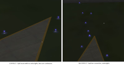
This picture shows the results – a split vertex with no attributes on the zero-length segment.
The next WED beta will automatically export split vertices this way – there will be no need to patch X-Plane or change your WED layouts.
In my previous blog post I defined a split vertex in an airport layout and described how they can be simulated in an apt.dat pile using multiple points.
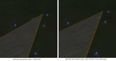
Now that WED is in public beta and people can easily make split beziers, many have noticed the “split bezier” bug in X-Plane 860:
This is a vertex that is split…on the left you can see what it should look like – on the right you can see what it does look like. There are two problems going on:
- The taxiway lights have gone crazy at the split vertex. (This is what everyone sees.)
- The taxiway line is a bit jumbled at the split vertex too.
It should be noted that this bug will can also happen for any vertex (even unsplit) in rare occaisions due to interactions with the mesh. Same symptom, same buggy code, different cause.
The good news is:
- There is a workaround that will make the lights look correct and the lines acceptable in X-Plane 8.60.
- The workaround will be implemented inside WED – no need to change anything.
- When X-Plane is fixed, it will make the lines correct too.
In my next post I’ll describe the fix and what the results look like.
(This blog entry explains the background of split beziers – the next parts will explain the bugs that they cause and the workarounds.)
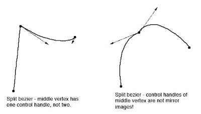
In apt.dat terminology, a split vertex is any vertex of a polygon where the control handles on either side of the vertex are not exact mirror images. (When there is only one control handle it is therefore by definition split!)
You need a split bezier any time you want to:
- Have a sharp corner between two curves and control the tangents of the curves or
- Have a sharp corner between a truly straight segment and control the curve of the next segment.
Split Beziers and apt.adt
Now here’s the rub: the apt.dat format does not allow for split beziers – each curved point has only one control handle – the other is calculated by x-plane by mirroring…thus no vertex can ever be split.
(This is due to a total lack of brains on my part when working on the apt.dat format, which is quite embarrassing considering how long I spent thinking about it.)
The Hack
There is a way to simulate a split bezier: if you use zero-length segments (that is, multiple points on top of each other), you can create a shape that works as if it is split.
In its simplest, a split bezier can be created by using 3 vertices.
- The first vertex uses the control handle of one side.
- The second vertex is not curved.
- The third vertex uses the control handle of the other side.
Why does this work? Well, a bezier curve between a curved point and a straight point has zero length if the two points are on top of each other. So what we’ve done is inserted two zero-length segments. The result of this mess is that the control handles on either “side” of this cluster of points can be different!
Is the second point really necessary! Yes! The reason is this: if we simply had the first and third point (two bezier points with different control handles), X-Plane would draw a loop from the first to the second. Remember: two colocated points with ONE control handle form a zero-length curve, but two colocated points with TWO control handles form a loop.
(To see this for yourself, just draw some examples in WED or photoshop. 🙂
Line Continuity
There is one more wrinkle we have to add to the puzzle in order to understand how this works, and what the pitfalls are: line continuity.
A bezier path (taxiway edge, linear segments, etc.) is made up of one or more bezier curves. Each curve has zero or more attributes.
When X-Plane draws the actual taxi lines and lights, it looks for continuous adjacent bezier curves with the same attribute and makes sure the linkage between those attributes is correct.
(This linkage is computed separately for each type of property. So if you have taxiway lines on two segments and lights on one, the taxiway lines will still link!)
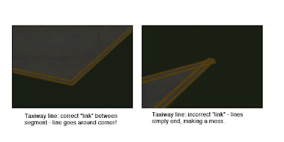
The picture above shows a correct vs. an incorrect link. When dealing with unsplit beziers and non-curved points, linkage is pretty much automatic, it just works.
But there is a pitfall to our above hack for split vertices: we have three points on top of each other. They must all have the same attributes in order for linkage to work. A “break” in the continuity of the line for one of the zero-length segments still counts as a break in linkage. The picture on the right was produced by creating a split bezier and removing the double-yellow-line attribute from the second of three vertices.
In my next post I’ll explain the bugs that this causes in X-Plane 8.60.


