With a new year and CES upon us, it’s go time for pundits to predict the future of the technology industry. Lori considered the question of how technology might affect X-Plane and pronounced:
Pixel shaders will get shadier.
I think she is right. It is only a question of how long until they are so shady that they are basically pitch black. (At that point, I expect a significant boost in framerates!)
There is no need to use the 3-d panel if you only want 3-d cockpit.
That might be the most counter-intuitive statement in the entire universe. Let’s break it down and see what’s going on. Originally we had the 2-D panel. The 2-D panel was where you put your instruments for interior views. When 3-d cockpit support was added, the 2-D panel was used to create the panel texture – that is, the instruments texture for the 3-D cockpit.
Thiat worked for a while, but as handles became more complex, screens became larger, and as 3-D cockpits became a more complex, authors started to run into the system’s limitations. If the author wanted to create a huge panel, then the panel texture for the 3-D cockpit was huge. Furthermore, texture space for the instruments in the 3-D cockpit was wasted because the 2-D panel had to have windows on it.
With X-Plane and 9 we added the 3-D panel to fix these problems. The 3-D panel is a second panel whose sole purpose is to provide instruments as a texture for the 3-D cockpit. When you have a 2-D panel and a 3-D panel, the 2-D panel is used to draw the panel in 2-D viewing modes and 3-D panel is used only to create the panel texture for the 3-D cockpit. With this setup the 2-D panel can be huge, and the 3-D panel can be small and compact with no windows.
The 3-D panel solves a second problem as well. Often the overhead panel is drawn in perspective on the 2-D panel this perspective view is useless for texturing a true 3-D cockpit. With a 2-D panel and a 3-D panel, the author can draw the overhead in perspective for the 2-D panel, and orthographically for the 3-D panel.
Now here’s where things get complicated: if an airplane has no 3-D panel the 2-D panel is used for both the 2-D view and the 3-D cockpit. But some airplanes have only a 3-D cockpit. In this case, there is no reason to use the 3-D panel at all. You can simply use the 2-D panel for texturing the 3-D cockpit and not worry about the user seeing it; in a 3-D only plane the user will only see the panel as a texture for the 3-D cockpit.
This setup is confusing in name: how can you have a 2-D panel used for a 3-D cockpits? But it is an allowed configuration. In fact, it was the only configuration allowed in X-Plane 8.
In summary: a 3-D cockpit can use the 2-D panel or 3-D panel as its panel texture. If an airplane has no 2-D panel, then the 2-D panel can be used for the 3-D cockpits without problems. In this situation and there is no need for a 3-D panel.
(It might be better to think of the 2-D panel and three panels simply add his two panels so that you can have two different versions of the panel. The names to the panel and 3-D panel are really just labels.)
Happy New Year! This entire post is going to be off topic, but hopefully worth it; I will resume the usual ranting about how video cards are slowly turning our brain into string cheese later.
I think my favorite part of working for Laminar Research and being part of the X-Plane community is the friends I have made in the X-Plane community – X-Plane really does bring a great group of people together. While I lived in California, I met Jay Oliver, and actually lived not too far from him while I was in ATC school.
Here’s the thing about Jay: he is a fabulous musician. In an age where music is “produced” and so much of what we hear is digitally manipulated, there’s a lot to be said for listening to a human being who is simply astoundingly good with his or her instrument. It’s an experience that can’t be synthesized. It was always enjoyable to get a few drinks into Jay and put him down in front of the Piano and then just listen.
I’ve been listening to Jay’s new album for a few days now, but Austin beat me to the punch, putting it on the X-Plane announce list. Jay set up his new website here, and his album is available for sale in CD or DRM-free mp3 format. You can also listen online right on the site.
Austin’s usual diet is highly electronic, usually runs at about 180 beats per minute, and is the musical equivalent of shooting Jolt cola directly into your brain. What Jay does is completely different, and it’s really something special.
It’s been a tough year for X-Plane authors. Key framing, manipulators, global lighting, baked lighting control, generic instruments, normal maps…version 9 has extended the possibilities for airplanes in a huge way. This is great for X-Plane users, and great for any author who wants to push the envelope, but there is a flip side: the time investment to make a “cutting edge” X-Plane aircraft has gone way, way up.
Here’s the problem: as hardware has been getting faster, the amount of data (in the form of detailed airplane models) needed to keep the hardware running at max has gone up. But the process of modeling an airplane hasn’t gotten any more efficient; all of that 3-d detail simply needs to be drawn, UV mapped and textured. Simply put, NVidia and ATI are making faster GPUs but not faster humans.
That’s why I was so excited about order independent transparency. This is a case where new graphics hardware and nicer looking hardware means less authoring work, not more. (The misery of trying to carefully manage ordered one sided geometry will simply be replaced by enabling the effect.)
My Daddy Can Beat Up Your Daddy
Cameron was on FSBreak last week last week discussing the new CRJ…the discussion touched on a question that gets kicked around the forums a lot these days: which allows authors to more realistically simulate a particular airplane…X-Plane 9 or FSX.
This debate is, to be blunt, completely moot. Both FS X and X-Plane contain powerful enough add-on systems that an author can do pretty much anything desired, including replacing the entire host simulation engine. At that point, the question is not “which can do more” because both can do more than any group of humans will ever produce. As Cameron observed, we’ve reached a point where the simulator doesn’t hold the author back, at least when it comes to systems modeling.
(It might be reasonable to ask: which simulator makes it easier to simulate a given aircraft, but given the tendency to replace the simulator’s built-in systems on both platforms, it appears the state of the art has gone significantly past built-in sim capabilities.)
Graphic Leverage
When it comes to systems modeling, the ability to put custom code into X-Plane or FS X allows authors to go significantly beyond the scope of the original sim. When it comes to graphics, however, authors on both platforms are constrained to what the sim’s native rendering engine can actually draw.
So if there’s a challenge to flight simulation next year, I think it is this: for next-generation flight simulators to act as amplifiers for the art content that humans build, rather than as engines that consume it as fuel. The simulator features that get our attention next year can’t just be the ability for an author to create something very nice (we’re already there), rather it needs to be the ability to make what authors make look even better.
(This doesn’t mean that I think that the platforms for building third party “stuff” are complete. Rather, I think it means that we have to carefully consider the amount of input labor it takes to get an output effect.)
I find it very difficult to write good documentation for the X-Plane scenery system and tools. Not only am I not a technical writer by training and not particularly good at explaining what I am thinking in non-technical terms, but since I have been working on the scenery system for over five years, I don’t really have good perspective as to what is complex and what is straightforward.
For this reason, I try to keep my ears open any time an author cannot understand the documentation, cannot find the documentation, or in another way has a problem with the scenery website. These “first experiences” give an idea of the real utility of the docs. Writing a reference for people who know things is not very hard – writing an explanation for new authors is much harder.
One author who was converting from MSFS to X-Plane pointed out a problem with the documentation that I hadn’t realized before – but I think he’s on to something. He pointed out that the information you need to complete a single project is often spread out all over the place. You probably need to look at an overview document, a file format, and a tool manual, each of which describes about 1/3 of the problem. To make it worse, each document assumes you know what the other ones say!
Who would write such poor documentation? A programmer, that’s who. (In other words, em.) In computer programming, the following techniques are all considered good design and essential:
- Breaking a problem into smaller, sections.
- Limited cross-references between these sections as much as possible.
- Keeping the sections independent.
- Not duplicating information (code).
In other words, the docs I have written for the scenery tools are a mess because they are “well factored”, a good thing for a C++ and a really useless thing for humans.
This is definitely not the only problem with the documentation, which also suffers from a lack of clarity, is often incomplete, and could use a lot more pictures. I am a programmer, and I am paid to make X-Plane faster, better, etc. It can be very hard to find the time to work on documentation when the next feature needs to be done. And yet…without documentation, who can use these features?
Now that I’ve at least figured out that factorization is bad, for the short term I am going to try to write “non-factored” documentation. The first test of this will be MeshTool. I am doing a complete rewrite of the MeshTool readme. Like the ac3d readme, MeshTool needs a full large-scale manual of perhaps 10-20 pages, and the task needs to be approached recognizing that the manual is going to contain a huge amount of information.
When I work on the MeshTool manual I will try to approach it from a task perspective, with explanations of the underlying scenery system, rather than a reference perspective that assumes authors might know why the given techniques work. We’ll see if this creates a more usable manual.
First, Merry Christmas and seasons greetings to, well, pretty much everyone – it’s been great to hear from everyone over the last week. I had a chance to poke at the scenery tools and have posted two new beta builds:
- MeshTool 2 beta 4.
- WED 1.1 developer preview 2.
You can download them both here.
MeshTool 2 beta 4 should be the last MeshTool beta short of bug fixes – that is, I’ve taken feature requests during the MeshTool beta, but I think we have what we need. Future feature enhancement will go in a later version.
Besides some useful bug fixes, there are two new features in this beta:
- You can specify a specific land class terrain with a shapefile.
- You can control the physical properties of orthophotos (are they wet or dry) with a shapefile without cropping out the water. This is useful for authors who want to use translucent orthophotos to create tinted water effects like coral or shallow sandy bottoms.
The WED developer preview simply puts up more bug fixes. WED isn’t quite beta because of one nasty limitation: the code that exports UV-mapped bezier curves doesn’t handle polygons that cross DSF boundaries. This code is going to be very difficult to get right – the combination of bezier curves, polygon cutting, and UV maps is a bit of a witches brew. Since WED isn’t really complete without this, I’m not calling the build a beta.
Also a docs update: I have posted the WED and Ac3d manuals in PDF form directly on the website. The AC3D manual (and motivation to do this) are thanks to Peter, who converted the manual from readme-text to PDF. I was shocked to realize the ac3d README is almost 20 pages. Hopefully having the manual in PDF form will help people realize just how much documentation is crammed in there.
X-Plane doesn’t natively and directly support popup panels, but that doesn’t mean you can’t pop them up. Generic instruments have a dataref-driven set of show-hide fields. (The “filters”.)
Now what you might not have realized is: groups have filters too! So you can hide an entire group with one filter, and you can put premade instruments in the group.
So…even though the FMS is a premade instrument with no filter fields, by grouping it you can show and hide it.
Important: the backgrounds of instruments are not shown or hidden. So if you want to do this, customize the FMS to have a transparent background, and use a generic rotary to put a real background behind it. The rotary goes in the group, and thus it can show and hide.
One more tip: clicking in 2-d goes through one instrument to another, for historical reasons. So if you pop up an instrument, you might want to hide the instruments it popped up over so clicks don’t affect them.
A quick tip to anyone using OpenGL and a plugin to make custom instruments. (The most common case of this I can imagine is customized glass displays, where it may not be practical to use 10,000 generic instruments, and the display being emulated is basically a computer display.)
OpenGL is not pixel exact, its per-primitive anti-aliasing (e.g. draw me a smooth line) is inconsistent and weird, and you probably won’t have full-screen anti-aliasing on your panel. (FSAA is out of your control, as X-Plane sets up the panel render.
For this reason, I recommend “texture anti-aliasing”. Basically in this technique you draw everything as rectangles, – for your lines, you use textures that have alpha at the edge. The linear intepollation of the texture forms the anti-aliased edge.*
For a detailed examination of the problem, I recommend this page. (arekkusu is a freaking genius and his treatment of the problem is very thorough!) I have also tried to explain how the hell OpenGL decides what it’s going to draw here. There are a few important cases where you can be pretty sure about what OpenGL will draw, and a lot of cases where you’re playing pixel roulette.
The “texture” technique also has the advantage that it leads nicely into the use of texture artwork. For example, if you need a line with an arrow-head, well, you’re already drawing a line as a textured rectangle with pixels in the center and alpha on the sides. Just ask your artist to draw an arrow-head in photoshop!
* Texture FSAA actually produces better results than FSAA (with non-AA pixels). The reason is that FSAA produces a finite number of intermediate alpha levels. The number of finite levels depends on the FSAA scheme, but it is always discrete levels, hence 16x FSAA looking better than 2x. By comparison, when we use textures, we get a smooth linear blend between our transparent and opaque pixels, giving us the smoothest possible anti-aliasing.
I have two fundamental “rants” about flight simulator scenery, and the way people discuss it, market it, compare it, and evaluate it. The rants basically go like this:
- Mesh resolution (that is, the spacing between elevation points in a mesh) is a crude way to measure the quality of a mesh. It is horribly inefficient to use 5m triangles to cover a flat plateau just because you need them for some cliffs.
- At some point, the data in a very high mesh becomes misleading. You have a 5m mesh. Great! Are you measuring a 5m change in elevation, or is that a parked car that has been included in the surface?
X-Plane uses an irregular mesh to efficiently use small triangles only where they are needed. I have some pictures on this here.
But it brings up the question: how good is a mesh? If you make a base mesh with MeshTool using a 10m input DEM (the largest DEM you can use right now), the smallest triangles might be 10m. But the quality of the mesh is really determined by the mesh’s “point budget” – that is, the number of points MeshTool was allowed to add to minimize error.
MeshTool beta 4 will finally provide authors with some tools to understand this: it will print out the “mesh statistics” – that is, a measure of the error between the original input DEM and the triangulation. Often the error* from using only 1/6th of the triangles from the original DEM might be as little as 1 meter.
I spent yesterday looking at the error metrics of the meshes MeshTool creates. I figured if I’m going to show everyone how much error their mesh has with a stats printout, I’d better make sure the stats aren’t terrible! After some debugging, I found a few things:
-
Vector features induce a lot of “error” from a metrics standpoint. Basically when you induce vector features, you limit MeshTool’s ability to put vertices where the need to be to reduce meshing error. The mesh is still quite good even with vectors, but if you could see where the error is coming from, the vast majority will be at vector edges.
For example, in San Diego the vector water is sometimes not quite in the flat part of the DEM, and the result is an artificial flattening of a water triangle that overlaps a few posts of land. If that land is fairly steep (e.g. it gains 10+ meters of elevation right off the coast) we’ll pick up a case where our “worst” mesh error is 10+ meters. The standard deviation will be
-
The whole question of how we measure error must be examined. My normal metric is “vertical” error – for a given point, how much is the elevation different. But we can also look at “distance” error: for a given point, how close is the nearest mesh point from the ideal DEM?
“Distance” mesh point gives us lower error statistics. The reason is because when we have a steep cliff, a very slight lateral offset of a triangle results in a huge vertical error, since moving 1m to the right might drop us 20 meters down. But…do we care about this error? If the effective result is the same cliff, offset laterally by 1m, it’s probably more reasonable to say we have “1m lateral error” than to say we have “20m vertical error”. In other words, small lateral errors become huge vertical errors around cliffs.
Absolute distance metrics take care of that by simply measuring the two cliff surfaces against each other at the actual orientation of the cliff. That is, cliff walls are measured laterally and the cliff floor is measured vertically. I think it’s a more reasonable way to measure error. One possible exception: for a landing area, we really want to know the vertical error, because we want the plane to touch pavement at just the right time. But since airplane landing areas tend to be flat, distance measurement becomes a vertical measurement anyway.
Unnatural Terrain
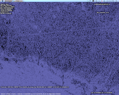
So there I am working with a void-filled SRTM DEM for KSBD. I have cranked the mesh to 500,000 points to measure the error (which is very low, btw…worst error 3m and standard deviation less than 15 cm.
But what are those horziontal lines of high density mesh?
I wasn’t sure what those were, but they looked way too flat and regular. So I look at the original DEM and I saw this:
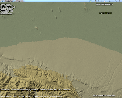
Ah – there are ridges in the actual DEM. Well that’s weird. What the heck could that be?
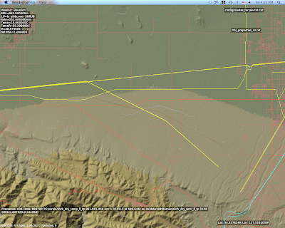
This is a view with vector data – and there you go. Those are power lines.
The problem in particular is that SRTM data is “first return” – that is, it is a measurement of the first thing the radar bounces off of from space. Thus SRTM includes trees, some large buildings, sky scrapers, and all sorts of other gunk we might not want. A mesh in a flight simulator usually represents “the ground”, but using first return data means that our ground is going to have a bump any time there is something fairly large on that ground. The higher the mesh res, and the lower the mesh error, the more of this real world 3-d coverage gets burned into the mesh.
So Do We Really Care About 5m DEMs?
The answer is actually yes, yes we do, but maybe not for the most obvious reasons.
The problem with raster DEMs (that is, an elevation as a 2-d grid of heights) is that it doesn’t handle cliffs very well. A raster DEM cannot, by its very format, handle a truly vertical cliff. In fact, the maximum slope it can create is based on
arctan(cliff height / DEM spacing)
Which is math to say: the tighter your DEM spacing, the higher the maximum slope we can represent for a given cliff at a certain height. Note that the total cliff height matters too, so even a crude 90m DEM like SRTM can represent a canyon if it’s really huge**, but we need a very high res DEM to get shorter vertical surfaces.
So the moderated version of my rant goes something like this:
- High res DEMs input DEMs are necessary to represent small terrain features that are steep if we are using raster DEMs.
- High res meshes are not necessary – we only need res for part of the mesh where it counts.
- Let’s not use mesh res to represent 3-d on the ground, only the ground itself.
There is another way to deal with elevation besides DEMs, and in fact it is used for LIDAR data (where the resolution is so high that a raster DEM would be unusable): you can represent a as a series of vector contour lines in 3-d. The beauty of contour lines is that they represent cliffs no matter how steep (up to vertical), and you don’t need a lot of storage if the ground is not very intricate.
The meshing data format inside MeshTool could probably be made t
o work with contours, but I haven’t seen anyone with high quality contour data yet. We’ll probably support such a feature some day.
* Really this should be “the additional error”, because when you get a DEM, it already has error – that is, the technique for creating the DEM will have some error vs. the real world. For example, if I remember right (and I probably do not) 90% of SRTM data points fall within 8m vertically of the real world values. So add MeshTool and you might be increasing the error from 8m to 9-10m, that is, a 12-25% increase in error.
** For the SRTM this might be a moot point – the SRTM has a maximum cliff slope in certain directions defined by the relationship between the shuttle’s orbit and the latitude of the area being scanned. The maximum cliff at any point in the SRTM is 70 degrees, which can be represented by a 247 m cliff using a pair of 90m posts.
This is getting embarrassing – I’m at risk of getting shut out. I was able to fix the “Null texture, how” error users were seeing on NVidia hardware.
It turns out it was an uninitialized variable in code that was never used until NV changed their drivers. As far as I can tell, NV dropped support for FSAA in 16-bit mode a few months ago, at least on some of their newer GPUs. (It is also possible that the incantation necessary to get FSAA has changed a lot and I simply don’t know what it is.)
So the dialog between X-Plane and the video card ran something like the Monty Python cheese shop sketch:
X-Plane: So … can you do full screen anti-aliasing?
GeForce 8: Oh yes, of course! (Please, I’m a GeForce 8 card.)
X-Plane: Splendid! So…how about 16x FSAA?
GeForce 8: Sorry, can’t I can’t do that.
X-Plane: Ah. How about 8x FSAA?
GeForce 8: Sorry, can’t do that either.
X-Plane: I see. Well then, how about 4x FSAA?
GeForce 8: Nope.
X-Plane: 2x FSAA?
GeForce 8: No way.
X-Plane: Ah. I see.
At this point in the dialog X-Plane would promptly lose track of what it had been doing in the setup process, throw out its notes on the GPU setup, and then freakout a bit later when it realized its note taking left something to be desired.
This is the first case I’ve hit where a video card advertises FSAA and can’t actually do it.
Anyway, if you have hit this bug:
-
Update to 941 final – it should fix it.
-
Stop trying to run with FSAA and 16-bit color. This is a somewhat crazy combination. FSAA attempts to clean up rendering artifacts at the cost of fill rate. 16-bit color creates artifacts to save fill rate. If your GPU needs 16-bit color to run at high framerate, it’s time to turn FSAA off.
(I realize that 16-bit color and aliasing are different kinds of artifacts, and some users might prefer harsh color transitions to harsh polygon transitions. But I still say, go for 32-bit color, no FSAA. When the sim is running in 16-bit mode, a good chunk of the sim still runs in 32-bit mode because 16-bit RGB surfaces only have 1 bit of alpha.* So you’re not quite getting universal savings but you get 16-bit output colors, so the results look universally bad.)
*This assumes 5551, or 565 pixels. There is a 4-bit alpha 16-bit color format, cleverly called 4444, but if you thought 16-bit looks bad…


